


IPmux-1/1E Installation and Operation Manual Appendix E Configuration Menus
IPmux-1 E1/T1 Configuration E-17
E.4 IPmux-1 E1/T1 Configuration
IPmux-1 automatically detects whether the interface is E1 or T1, and the
appropriate menu appears (see Figure E-24 and Figure E-25).
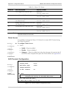
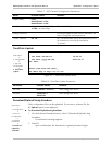
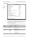
E1 Configuration
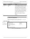
E1 CONFIGURATION
1. Channel Status Enable
2. Transmit Clock Source Adaptive
3. Loopback State Disable
4. Rx. Sensitivity -10dB
5. Line Type CRC4 enable
6. Idle Code 7E
7. Uplink Fail Alarm Behavior Cond.
8. Signaling Mode CAS enable
9. Cond. Data Pattern FF
A. Cond. CAS (ABCD) Pattern 01
ESC. Exit
Select item from the menu.
Use <Esc> key or keys <1> to <9>
Figure E-24. E1 Physical Layer Configuration Menu
When “unframed” mode is selected, the Idle Code, Signaling Mode, Cond Data
Pattern and Cond CAS Pattern fields are not present.
When CAS Disabled is selected, the Cond CAS Pattern field is not present.
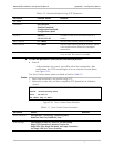
Table E-12. E1 Physical Layer Configuration Parameters
Parameter Possible Values Remarks
Channel Status
Enable
Disable
Detection of LOS alarm
No detection of LOS alarm
Default: Enable
Transmit Clock Source
Adaptive
Loopback
Internal
Adaptive clock regeneration
E1 recovered receive clock is used as the transmit clock
Local clock source is used
Default: Adaptive
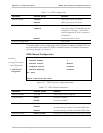
Note
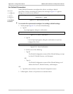
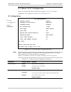
Main Menu
↓
2. Configuration (E1)
↓
2. E1/T1
Configuration