


IPmux-1/1E Installation and Operation Manual Appendix E Configuration Menus
IPmux-1E Configuration E-25
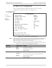
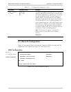
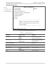
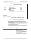
Analog Configuration
ANALOG CONFIGURATION
1. Clock Source Adaptive
2. Far End Type E1
3. Channel Configuration >
4. Signaling Profile Configuration >
5. Signaling Feedback
6. Signaling Mode
7. Wiring
ESC. Exit
+----------------------------------------+
|NOTICE: The connection must be disabled |
|before changing the Clock Source or the |
| Far End Type! |
+----------------------------------------+
Select item from the menu.
Figure E-28. Analog Configuration Menu
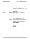
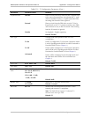
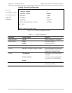
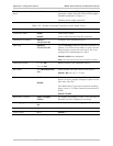
Table E-16. Analog Configuration
Parameter Possible Values Remarks
Clock Source
Internal
Adaptive
Local clock source is used
Adaptive clock regeneration
Far End Type
E1
T1-ESF, T1-D4
Sets A-Law/µ-Law and TDMoIP
encapsulation mode
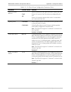
Channel Configuration
Next screen
Signaling Profile Configuration
Next screen
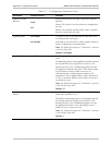
Signaling Feedback
Valid only for FXO
Signaling Mode
Type1, Type2, Type3, Type5
(SSDC5)
Valid only for E&M
Wiring
2-Wire, 4-Wire
Valid only for E&M
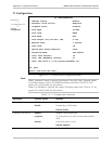
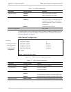
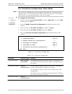
Main Menu
↓
2. Configuration (Analog)
↓
2. Analog Configuration