


Chapter 1 Introduction IPmux-1/1E Installation and Operation Manual
1-18 Functional Description
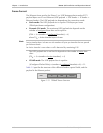
VLAN Support
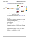
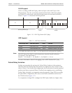
VLAN, according to IEEE 802.1p&q, adds four bytes to the MAC layer of the
Ethernet frame. The user can set the contents of these bytes, MAC layer priority
and VLAN ID. In this mode, only VLAN format frames are sent and received by
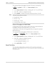
IPmux-1. Figure 1-16 shows the VLAN tag format.
802.1D Tag Protocol Type
81 00
user_priority
CFI = 0
VID
8654 18 1
Priority
VLAN ID
Figure 1-16. VLAN Tag Format (802.1p&q)
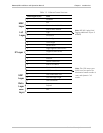
UDP Support
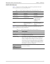
Table 1-3. UDP Ports Definition
Field Length (Bits) Field Description Value Function
2 bytes UDP Source Port 2–497d* Destination timeslots bundle
2 bytes UDP Destination Port 2142d Standard TDMoIP UDP port
* The MSB of this field can be either 1 or 0 for inband end-to-end proprietary signaling.
The UDP Source Port field is used for destination timeslots bundle indication.
For example, if the destination is:
Bundle 1 – 02, Bundle 2 – 03, Bundle 3 – 04, Bundle 4 – 05, etc.
For more information about VLAN tagging, refer to IEEE Standard 802.1p&q.
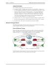
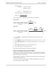
Packet Delay Variation
Packets are transmitted at set intervals. Packet Delay Variation is the maximum
deviation from the nominal time the packets are expected to arrive at the far end
device. IPmux-1 has a buffer that compensates for the deviation from the expected
packet arrival time to prevent IPmux-1 buffers from emptying out or overflowing.
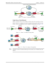
Packet Delay Variation is an important network parameter. Large PDV (exceeding
the jitter buffer configuration) will cause receive buffer underflows and errors at
the TDM level (see Figure 1-17).
To compensate for large PDV, configure the PDVT (jitter) buffer to a higher value.
Note