


Chapter 2 Installation IPmux-1/1E Installation and Operation Manual
2-10 Installation and Setup
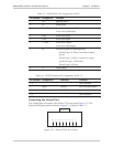
Table 2-7. External Clock Port Pinout
Pin Number Signal Name Function
1 RRING Rx
2 RTIP Rx
3 GND Usually not connected
4 TRING Tx
5 TTIP Tx
6 GND Usually not connected
7 – Not connected
8 – Not connected
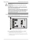
Connecting the Power
To connect power to IPmux-1/1E, refer to the appropriate section below,
depending on your version of the unit (AC or DC).
AC Power Connection
AC power is supplied to IPmux-1/1E through the 5-ft (1.5m) standard power cable
terminated by a standard 3-prong plug. The cable is supplied with the unit.
To connect AC power to IPmux-1/1E:
1. Verify that the AC outlet is grounded properly. Ensure that the supply voltage is
in the range 100 VAC to 240 VAC.
2. Check that the Power switch on the rear panel is set to OFF.
3. Connect the power cable to the rear panel connector first and then to the
AC mains outlet.