


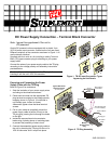


DC Power Supply Connection – Terminal Block Connector
Note: Ignore this supplement if the unit is
AC-powered.
Certain DC-powered units are equipped with a plastic 3-pin
VDC-IN power input connector, located on the unit rear panel.
Different variations of the connector are shown in Figure 1. All
are functionally identical.
Supplied with such units is a kit including a mating Terminal
Block (TB) type connector plug for attaching to your power
supply cable.
Connect the wires of your power supply cable to the TB plug,
according to the voltage polarity and assembly instructions
provided below.
Caution: Prepare all connections to the TB plug before
inserting it into the unit’s VDC-IN connector.
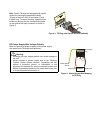
Preparing and Connecting the Power
Supply Cable with the TB Plug
Refer to Figure 2 for assistance.
1. Strip the insulation of your power supply wires
according to the dimensions shown.
2. Place each wire lead into the appropriate TB
plug terminal according to the voltage polarity
mapping shown in Figure 4. (If a terminal is
not already open, loosen its screw).
Afterwards, tighten close the three terminal
screws.
3. Pull a nylon cable tie (supplied) around the
power supply cable to secure it firmly to the
TB plug grip, passing the tie through the holes
on the grip.
4. Isolate the exposed terminal screws/wire
leads using a plastic sleeve or insulating tape,
to prevent the possibility of short-circuit.
5. Connect the assembled power supply cable to
the unit by inserting the TB plug into the unit’s
VDC-IN connector until it snaps into place.
BCA
ED
Figure 1. TB DC Input Connectors Types
Appearin
g
on Unit Panels
Typical DC Power
Input Connector
(on unit panel)
Mating
TB Connector
Plug
See following page
for wire mapping
Terminal screws
Wire stripping
dimensions
DC power
cable
Nylon cable tie
TB plug grip
5 mm
20 mm
Figure 2. TB Plug Assembly
SUP-220-03/03