


Chapter 1 Introduction IPmux-1/1E Installation and Operation Manual
1-2 Overview
• IPmux-1E with E1 interface and an echo canceller
Balanced line with an RJ-45 connector
Unbalanced line with a mini-coaxial connector (TBNC)
• IPmux-1E with T1 interface and an echo canceller
Balanced line with an RJ-45 connector
Unbalanced line with a mini-coaxial connector (TBNC).
An external clock port is optional for IPmux-1/1E (Ordering options).
A user Ethernet interface is optional for IPmux-1/1E (Ordering options).
Options
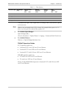
IPmux-1/1E is a 1U high, easy-to-install standalone unit. A rack mount installation
option is available: RM-25 for IPmux-1, and RM-26 for IPmux-1E.
IPmux-1 can be ordered with AC or DC power supply. IPmux-1E is only available
with AC power supply.
Applications
Typical IPmux-1/1E applications are shown with E1/T1, ISDN, and FXS/FXO/E&M
interfaces.
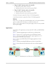
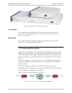
Figure 1-1 illustrates Multiplexing Voice and Data over an Ethernet link.
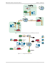
Figure 1-2 shows an E1/T1 circuit extension over an IP/Ethernet Network.
Figure 1-3 illustrates mixed ISDN BRI and POTS support application of V5.1
concentration of ISDN BRI remote terminals.
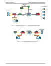
Figure 1-4 shows mixed ISDN BRI and POTS support application of Voice
Concentration.
Figure 1-5 illustrates extending ISDN BRI ports and LAN of a Small Office.
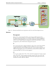
Figure 1-6 shows Ethernet-based multi-tenant with voice and data integrated
access.
E1/T1
IPmux-1
PBX
SITE B
10/100 Mbps
10/100 Mbps
E1/T1
IPmux-1
PBX
SITE A
IP/Ethernet
Network
Figure 1-1. Multiplexing Voice and Data over an IP/Ethernet Link