


Chapter 2 Installation IPmux-1/1E Installation and Operation Manual
2-6 Installation and Setup
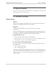
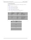
IPmux-1E
Figure 2-6. IPmux-1E Front Panel
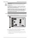
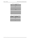
IPmux-1E
Figure 2-7. IPmux-1E Front Panel for Two Ethernet Ports
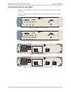
100-240 VAC
1.6A T 250V
POWER
I/O
3
:
CAUTION
IISDN
S
1234
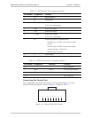
Figure 2-8. IPmux-1E Rear Panel (ISDN BRI Option)
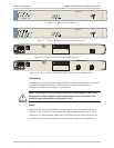
100-240 VAC
1.6A T 250V
POWER
I/O
3
:
CAUTION
IISDN
S
1234
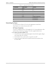
Figure 2-9. IPmux-1E Rear Panel (ISDN BRI Option) for Two Ethernet Ports
Grounding
Interrupting the protective grounding conductor (inside or outside the instrument)
or disconnecting the protective earth terminal can make this instrument
dangerous. Intentional interruption is prohibited.
Before switching ON this instrument and before connecting any other cable,
the protective earth terminals of this instrument must be connected to the
protective ground conductor of the power cord.
Fuses
Make sure that only fuses with the required rated current and specified type, as
marked on the IPmux-1/1E rear panel, are used for replacement: 1.6A T 250V.
Whenever it is likely that the protection offered by fuses has been impaired, the
instrument must be made inoperative and secured to prevent any operation.
Warning