


Chapter 1 Introduction IPmux-1/1E Installation and Operation Manual
1-14 Functional Description
ISDN/FXS/FXO/E&M
The available timing modes for the PCM clock are:
• Loopback Timing – available only when IPmux-1E ISDN BRI is configured as
TE (not available in ISDN BRI NT mode or for FXS/FXO/E&M interface). In this
mode the PCM clock is derived from Channel 1. It is recommended not to
deactivate Channel 1 while it is in loopback clock so that data will not be
damaged. If Channel 1 is disconnected or deactivated (by the NT side), the
PCM clock will change to Internal clock and a momentary disruption will
occur to the other channels (2,3,4), if they are active.
• Adaptive Mode – the clock is regenerated using the Adaptive method, where
the rate of arriving packets is used to regenerate the clock (see E1/T1, above).
• Internal Mode – the clock is received from an internal oscillator.
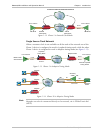
Network Timing Schemes
The following paragraphs describe typical timing schemes and the correct timing
mode settings for achieving end-to-end synchronization.
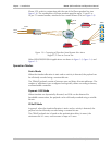
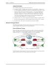
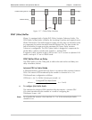
External Network Timing
When the edges of the network are synchronized by an external network clock
source, all the IPmux-1 units should be configured to work in loopback timing
mode (see Figure 1-11). This topology enables any-to-any connectivity.
E1/T1 Device
E1/T1
E1/T1
Clock from External Distribution Network
IPmux-1
E1/T1 Device
E1/T1
E1/T1
LBT Mode
IPmux-1
E1/T1 Device
E1/T1
E1/T1
LBT Mode
E1/T1 Device
IPmux-1
LBT Mode
IPmux-1
LBT Mode
IP/Ethernet
Figure 1-11. IPmux-1 in Loopback Timing Mode
External timing from the network can also be issued to IPmux-1 by External Clock
input; in this case, the E1/T1 device will use the LBT mode.