


1-2
Cisco ME 6500 Series Ethernet Switch Installation Guide
OL-8900-03
Chapter 1 Product Overview
Cisco ME 6524 Ethernet Switch (ME-C6524GS-8S)
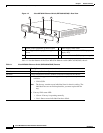
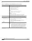
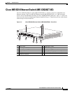
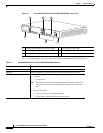
Figure 1-2 Cisco ME 6524 Ethernet Switch (ME-C6524GS-8S)—Rear View
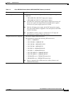
Table 1-1 lists the features of the Cisco ME 6524 Ethernet switch (ME-C6524GS-8S) chassis.
1 System ground pad/NEBS ground location 4 Power supply status LEDs
2 Power supplies (DC-input power supplies
shown)
5 Power supply terminal block (DC-input power
supply only)
3 Fan tray 6 Power on/off switch (DC-input power supply)
147978
INPU
T
O
K
OU
TPU
T
OK
FAN
OK
INPUT
O
K
O
UTP
UT
O
K
FAN
OK
o
o
+
-
+
-
1
2
456
3
Table 1-1 Cisco ME 6524 Ethernet Switch (ME-C6524GS-8S) Features
Feature Description
Chassis 1.5 RU height, fixed configuration chassis
Modules Fixed configuration chassis; modules cannot be installed in the chassis.
Fan tray • The chassis supports one hot-swappable fan tray. One fan tray model is
available:
–
FAN-C6524
Note The fan tray contains seven individual fans for chassis cooling. The
individual fans are not field replaceable; you must replace the fan
tray.
• Fan tray FAN status LED
–
Green—Fan tray is operating normally.
–
Red—One or more individual fans have failed.