


3-9
Cisco ME 6500 Series Ethernet Switch Installation Guide
OL-8900-03
Chapter 3 Installing the Switch
Connecting Source Power to the Chassis
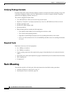
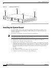
To attach the grounding lug and cable to the grounding pad, follow these steps:
Step 1 If you are using insulated wire, use a wire-stripping tool to remove approximately 0.75 inch (19 mm) of
the covering from the end of the grounding wire. If you are using bare wire, go to Step
2.
Step 2 Insert the stripped end of the grounding wire into the open end of the grounding lug.
Step 3 Crimp the grounding wire in the barrel of the grounding lug. Verify that the ground wire is securely
attached to the ground lug.
Step 4 Place the grounding wire lug against the grounding pad, making sure that there is solid metal-to-metal
contact.
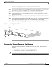
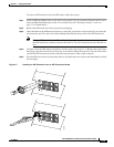
Step 5 Secure the grounding lug to the chassis with two M4 screws. (See Figure 3-4.) Ensure that the grounding
lug and the grounding wire do not interfere with other switch hardware or rack equipment.
Step 6 Prepare the other end of the grounding wire, and connect it to an appropriate grounding point in your
site to ensure adequate earth ground for the switch.
Figure 3-4 Installing the System Ground
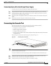
Connecting Source Power to the Chassis
This section provides instructions on connecting source power to the chassis. Two procedures are
provided:
• Connecting Source DC to the DC-Input Power Supply, page 3-10
• Connecting Source AC to the AC-Input Power Supply, page 3-11
Note The ME6524 switches support mixing AC-input and DC-input power supplies in the same chassis.
147982
INPUT
O
K
O
UTPUT
O
K
FAN
O
K
INPU
T
O
K
OU
TPU
T
OK
FA
N
OK
o
o
+
-
+
-
(M4)
Phillips-head
machine
screws
System
ground
pad
System
ground
wire
Ground
lug