


2-10
Cisco ME 6500 Series Ethernet Switch Installation Guide
OL-8900-03
Chapter 2 Preparing for Installation
Power Requirements
Power Connection Guidelines for AC-Powered Systems
This section provides basic guidelines for connecting AC-input power supplies to site source AC.
• In some systems, you may decide to use an uninterruptible power supply (UPS) to protect against
power failures at your site. Be aware when selecting a UPS that some UPS models that use
ferroresonant technology can become unstable when operating with the ME
6524 switch power
supplies that use power factor correction (PFC). This configuration can cause the output voltage
waveform to the switch to become distorted resulting in an undervoltage situation in the system.
• In systems configured with two power supplies, connect each of the two power supplies to a separate
input power source. If you fail to do this, your system might be susceptible to total power failure
due to a fault in the external wiring or a tripped circuit breaker.
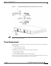
• The AC-input power supply has a detachable power cord that allows you to connect each power
supply to the site power source.
• To prevent a loss of input power, be sure that the total maximum load on each source circuit is within
the current ratings of the wiring and breakers.
• If you are using a 200/240 VAC power source in North America, the circuit must be protected by a
two-pole circuit breaker.
• Ensure that all power connection wiring conforms to the rules and regulations in the National
Electrical Code (NEC) and any additional local codes.
• The source AC outlet must be within 6 feet (1.8 meters) of the system and should be easily
accessible.
• The AC power receptacles used to plug in the chassis must be the grounding type. The grounding
conductors that connect to the receptacles should connect to protective earth ground at the service
equipment.
• The circuit breaker is considered the disconnect device and should be easily accessible.
• You must protect the circuit by using a dedicated two-pole circuit breaker. The circuit breaker should
be sized according to the power supply input rating and local or national code requirements.
Power Connection Guidelines for DC-Powered Systems
This section provides basic guidelines for connecting DC-input power supplies to site source DC.
When preparing your site for the switch installation, follow these requirements:
• In systems configured with two power supplies, connect each of the two power supplies to a separate
input power source. If you fail to do this, your system might be susceptible to total power failure
due to a fault in the external wiring or a tripped circuit breaker.
• To prevent a loss of input power, be sure that the total maximum load on each source circuit is within
the current ratings of the wiring and breakers.
• You can connect the DC-input power supply to the power source with heavy gauge wiring with either
insulated crimp-on spade lugs or insulated crimp-on ring connectors connected to a terminal block.
The wire gauge size and connector size is determined by local electrical codes and restrictions.
• Ensure that all power connection wiring conforms to the rules and regulations in the National
Electrical Code (NEC) and any additional local codes.
• Ensure that the DC return remains isolated from the system frame and the chassis (DC-I).