


1-10
Cisco ME 6500 Series Ethernet Switch Installation Guide
OL-8900-03
Chapter 1 Product Overview
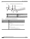
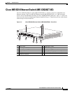
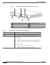
Cisco ME 6524 Ethernet Switch (ME-C6524GT-8S)
Chassis front panel features
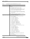
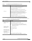
STATUS LED The STATUS LED indicates the system health.
• Green—The system is operating normally.
• Red—A fault has been detected in the system.
• Amber—System is booting up.
• Off—The system is not powered up.
PS1 (Power supply 1) LED The PS1 LED indicates the status of the power supply installed in power
supply bay
1.
• Green—Power supply is on and the input and output voltages are OK.
• Red—The power supply has a fault.
• Off—The power supply is off or is not installed.
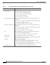
PS2 (Power supply 2) LED The PS2 LED indicates the status of the power supply installed in power
supply bay
2.
• Green—Power supply is on and the input and output voltages are OK.
• Red—The power supply has a fault.
• Off—The power supply is off or is not installed.
FAN The FAN LED indicates the status of the individual fans in the fan tray.
• Green—Fan tray is operating normally.
• Red—One or more individual fans in the fan tray have failed.
RESET switch A recessed switch allows the user to reset the system.
Console port A single console port allows the user access to the command-line interface.
The console port has an RJ-45 connector.
USB ports The switch has two USB ports:
• Port 1 is a device port with a Type B USB connector. A standard
USB
1.1 host, such as a PC, can plug into this port.
• Port 2 is a host port with a Type A USB connector. A standard USB 1.1
device, such as flash memory, can plug into this port.
PCMCIA connector Type 2 CompactFlash devices can be plugged into this connector.
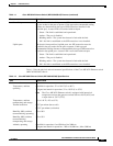
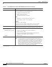
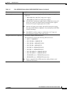
Table 1-3 Cisco ME 6524 Ethernet Switch (ME-C6524GT-8S) Features (continued)
Feature Description