


3-12
Cisco ME 6500 Series Ethernet Switch Installation Guide
OL-8900-03
Chapter 3 Installing the Switch
Installing the SFP Transceivers
Step 4 Check the terminal documentation to determine the baud rate. The baud rate of the terminal must match
the default baud rate (9600 baud) of the console port. Set up the terminal as follows:
• 9600 baud
• 8 data bits
• No parity
• 2 stop bits
Installing the SFP Transceivers
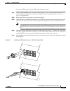
These sections describe how to install the SFP transceivers. SFP transceivers are inserted into the
downlink and uplink SFP sockets on the front of the Cisco
ME 6524 Ethernet switch. These
field-replaceable transceivers provide the downlink and the uplink optical interfaces.
You can use any combination of SFP transceivers. The only restriction is that each port must match the
wavelength specifications on the other end of the cable, and the cable must not exceed the stipulated
cable length for reliable communications.
Use only Cisco SFP transceivers on the Cisco ME 6524 Ethernet switch. Each SFP transceiver has an
internal serial EEPROM that is encoded with security information. This encoding allows Cisco to
identify and validate that the SFP transceiver meets the requirements for the switch.
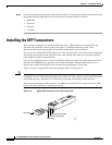
Figure 3-6 shows an optical SFP transceiver equipped with a bail-clasp latch.
Caution We strongly recommend that you do not install or remove the SFP transceiver with fiber-optic cables
attached to it because of the potential damage to the cables, the cable connector, or the optical interfaces
in the SFP transceiver. Disconnect all cables before removing or installing an SFP transceiver.
Removing and installing an SFP transceiver can shorten its useful life. Do not remove and insert SFP
transceivers more often than is absolutely necessary.
Figure 3-6 Optical SFP Transceiver with a Bail-Clasp Latch
130927
G
L
C
-S
X
-M
M
C
la
s
s
1
2
1
C
F
R
1
0
4
0
.1
0
L
N
#
5
0
7
/0
1
0
3
-
1
3
S
/N
:
O
H
1
2
3
3
4
5
6
Receive optical bore
Transmit optical bore
Bail clasp
Dust plug