


4-5
Cisco ME 6500 Series Ethernet Switch Installation Guide
OL-8900-03
Chapter 4 Removal and Replacement Procedures
Removing and Installing the DC-Input Power Supply
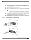
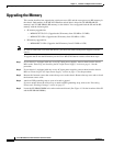
Step 9 Connect the DC-input wires to the terminal block in this order:
1. Ground cable to the ground connector on the terminal block
2. Negative (–) source DC cable to the negative (–) connector on the terminal block
3. Positive (+) source DC cable to the positive (+) connector on the terminal block
Step 10 After ensuring that all wire connections are secure, reinstall the plastic terminal block cover.
Caution To prevent a short circuit or shock hazard after wiring the DC-input power supply, you must reinstall the
terminal block cover.
Caution In a system with dual power supplies, connect each power supply to a separate power source. In case of
a power source failure to one supply, the second power source should still be available.
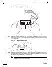
Step 11 Remove any safety flag and lockout devices or any tape from the circuit breaker switch handle, and
restore power by moving the circuit breaker switch handle to the on (|) position.
Step 12 Set the power switch to the on (|) position on the power supply.
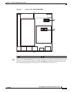
Step 13 Verify the power supply operation by ensuring that the power supply front panel LEDs are in these states:
• INPUT OK LED is green
• FAN OK LED is green
• OUTPUT OK is green