


4-13
Cisco ME 6500 Series Ethernet Switch Installation Guide
OL-8900-03
Chapter 4 Removal and Replacement Procedures
Upgrading the Memory
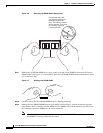
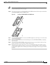
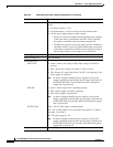
Caution When inserting the DIMM, use firm but not excessive pressure. If you damage a socket, you will have
to return the main board to Cisco for repair.
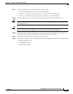
Step 10 Press down on the edges of the DRAM DIMM until the DIMM socket tabs click into place on both sides
of the DRAM DIMM locking the DIMM in place.
Figure 4-8 Installing the DRAM DIMM in the DIMM Socket
Step 11 Locate the RP DRAM DIMM in its socket on the MSFC daughter card. (See Figure 4-5 for the location
of the RP DRAM DIMM.)
Step 12 Repeat the DRAM DIMM removal and installation process for the RP DRAM DIMM by completing
steps 4 through 8.
Step 13 After replacing both DRAM DIMMs, position the chassis top cover over the chassis and lower it into
position. Secure the cover to the chassis with the fourteen screws.
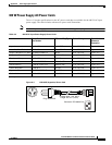
Step 14 Reinstall the power supplies in the chassis. If you are reinstalling DC-input power supplies, refer to
“Installing the DC-Input Power Supply” section on page 4-4 for the procedure. If you are reinstalling
AC-input power supplies, refer to “Installing the AC-Input Power Supply” section on page 4-8 for the
procedure.
130913