


4-9
Cisco ME 6500 Series Ethernet Switch Installation Guide
OL-8900-03
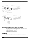
Chapter 4 Removal and Replacement Procedures
Removing and Installing the Fan Tray
Removing the Fan Tray
The fan assembly can be removed and replaced while the system is operating without presenting an
electrical hazard to the user or damage to the system.
Warning
When removing the fan tray, keep your hands and fingers away from the spinning fan blades. Let the
fan blades completely stop before you remove the fan tray.
Statement 258
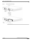
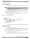
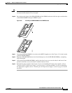
To remove the installed fan assembly, follow these steps:
Step 1 Loosen the captive installation screw.
Step 2 Grasp the fan assembly handle, and pull it outward; rock it gently, if necessary, to unseat the fan tray
power connector from the chassis connector. (See
Figure 4-4.)
Step 3 Place your free hand under the fan tray to support it. Pull the fan assembly clear of the chassis, and put
it in a safe place. (See
Figure 4-4.)
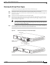
Figure 4-4 Removing and Installing the Fan Tray
Installing the Fan Tray
To install the new fan tray, follow these steps:
Step 1 Remove the replacement fan tray from its shipping packaging.
Step 2 Position the fan assembly in front of the fan tray bay at the rear of the chassis. (See Figure 4-4.)
Step 3 Slide the fan tray into the fan tray bay until the power connector seats in the chassis fan connector and
the captive installation screw makes contact with the chassis.
Step 4 Tighten the captive installation screw.