


2-11
Cisco ME 6500 Series Ethernet Switch Installation Guide
OL-8900-03
Chapter 2 Preparing for Installation
Cabling Requirements
• For DC power cables, we recommend that you use commensurately rated, high-strand-count copper
wire cable. Connection to the DC-input power supply requires one earth ground cable, one source
DC (–), and one source DC return (+). The length of the cables depends on your switch location.
These cables are not available from Cisco Systems. They are available from any commercial cable
vendor.
• The color coding of the source DC power cable leads depends on the color coding of the site DC
power source. Typically, green or green and yellow indicate that the cable is a ground cable. Because
there is no color code standard for source DC wiring, you must ensure that the power cables are
connected to the DC-input power supply terminal block in the proper (+) and (–) polarity. In some
cases, the source DC cable leads might have a positive (+) or a negative (–) label. This label is a
relatively safe indication of the polarity, but you must verify the polarity by measuring the voltage
between the DC cable leads. When making the measurement, the positive (+) lead and the negative
(–) lead must always match the (+) and (–) labels on the DC-input power supply terminal block.
• You must terminate DC power cables by using insulated crimp-on spade lugs or insulated crimp-on
ring connectors at the power supply end.
• The circuit breaker is considered the disconnect device and should be easily accessible.
• You must protect the circuit by using a dedicated two-pole circuit breaker. The circuit breaker should
be sized according to the power supply input rating and local or national code requirements.
Cabling Requirements
When running power and data cables together in overhead cable trays or subfloor cable trays, be aware
of the following cautions:
Caution We strongly recommend that you locate the power cabling runs and other potential noise sources as far
away as practical from LAN cabling that terminates on Cisco equipment. If you cannot separate the long
parallel cable runs by at least 3.3
feet (1 meter), we recommend that you shield these potential noise
sources by housing them in grounded metallic conduits.
Caution The intrabuilding port(s) of the equipment or subassembly is suitable for connection to intrabuilding or
unexposed wiring or cabling only. The intrabuilding port(s) of the equipment or subassembly must not
be metallically connected to interfaces that connect to the Outside Plant (OSP) or its wiring. These
interfaces are designed for use as intrabuilding interfaces only (Type
2 or Type 4 ports as described in
GR-1089-CORE, Issue
4) and require isolation from the exposed OSP cabling. Do not use a Primary
Protector when making a connection; Primary Protectors will not provide sufficient protection if you
connect these interfaces metallically to OSP wiring.
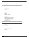
Site Preparation Checklist
Table 2-2 lists the site planning activities that you should perform prior to installing the Cisco ME 6524
Ethernet switch. Completing each activity helps ensure a successful switch installation.