


5-4
Cisco Service Control Engine 1000 2xGBE Quick Start Guide
OL-7822-06
Chapter 5 Cable the Line Ports
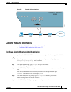
Cabling the Line Interfaces
Returns to Global Configuration Mode, from which you can enter the GigabitEthernet Interface
configuration mode for the remaining GBE port.
Repeat this procedure to configure auto-negotiation for the other GBE port interface.
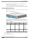
Connect the GBE Line Interface Ports
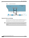
Refer to Information About Cabling, page 5-1 to find the appropriate cabling diagram for the topology
of your system.
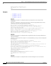
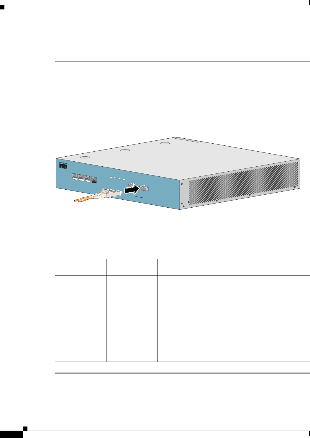
Figure 5-3 Cabling the GBE Interface
The following table presents the fiber specifications. The SCE 1000 may be ordered with either
Multimode or Single Mode transceivers The transceiver type is indicated on the front panel under the
ports. Note that both transceivers on any individual SCE 1000 are the same, either 850nm Multimode
OR 1310 Single Mode.
Step 1 Plug the specified fiber optic cable (see table above) into the appropriate GBE port on the front panel of
the SCE 1000.
Step 2 Verify that the link LED is green.
C
isco S
C
E
1000
Series
2xG
B
E
L
I
N
K
R
X
T
X
R
XM
MT
X
L
I
N
K
R
X
T
X
R
X
M
M
T
X
G
B
E
-
1
S
U
B
L
I
N
EN
E
T
P
W
R
B
S
T
A
T
U
S
P
W
R
A
B
Y
P
A
S
S
1
0
/
1
0
0
/
1
0
0
0
L
I
N
K
/
A
C
T
I
V
E
1
0
/
1
0
0
/
1
0
0
0
L
IN
K
/
A
C
T
I
V
E
A
U
X
C
O
N
S
O
L
E
M
N
G
2
M
N
G
1
92962
Table 5-1 Fiber Specifications
SCE Model Transceiver Transmit Power Receive Power
Typical (Max.)
Distance
SCE 1000 2xGBE
MM
850nm Multimode –9.5 to –4 dBm –17 to 0 dBm
• 750m for
50µm Core
Diameter
MMF
• 400m for
62.5µm Core
Diameter
MMF
SCE 1000 2xGBE
SM
1310nm FRP laser
Single Mode
–9.5 to –3 dBm –20 to 3 dBm 10 km for 9.0µm
Core Diameter
SMF