


1-4
PA-2FE-TX and PA-2FE-FX Two-Port Fast Ethernet Port Adapter Installation and Configuration
OL-3474-07
Chapter 1 Overview
LEDs
Note PA-2FE-FX uses 62.5/125-micron multimode fiber with an SC connector.
LEDs
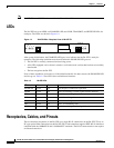
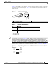
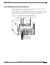
The PA-2FE has seven LEDS; an ENABLED LED, and LINK, TRANSMIT, and RECEIVE LEDs for
each port. The LEDs are shown in Figure 1-4.
Figure 1-4 PA-2FE LEDs—Faceplate View of PA-2FE-TX
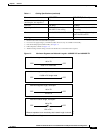
After system initialization, the ENABLED LED goes on to indicate that the PA-2FE is ready for
operation. The following conditions must be met before the ENABLED LED goes on:
• The PA-2FE is correctly connected and receiving power.
• A PA-2FE–equipped card or chassis contains a valid microcode version that has been successfully
downloaded.
• The bus recognizes the PA-2FE.
If any of these conditions are not met, or if the initialization fails for other reasons, the ENABLED LED
does not go on. Table 1-2 lists LED colors and indicator functions.
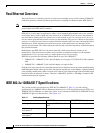
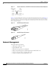
Receptacles, Cables, and Pinouts
The two interface receptacles on the PA-2FE are a single RJ-45 connection (on the PA-2FE-TX) or an
SC-type optical-fiber connection (on the PA-2FE-FX). Each connection supports IEEE 802.3u interfaces
compliant with the 100BASE-X and 10/100BASE-T standards. The RJ-45 connection does not require
an external transceiver.
46453
ENABLED
LINK0
TX0
RX0
RX1
LINK1
TX1
PA-2FE-TX
0
1
Table 1-2 PA-2FE LEDs
LED Label Color State Function
ENABLED Green On Port adapter is enabled for operation.
LINK0 Green On Port 0 is receiving a carrier signal from the network.
1
1. When an RJ-45 or SC port is active.
TX0 Green On Port 0 is transmitting data.
RX0 Green On Port 0 is receiving data.
RX1 Green On Port 1 is receiving data.
TX1 Green On Port 1 is transmitting data.
LINK1 Green On Port 1 is receiving a carrier signal from the network.
1