


1-5
PA-2FE-TX and PA-2FE-FX Two-Port Fast Ethernet Port Adapter Installation and Configuration
OL-3474-07
Chapter 1 Overview
Receptacles, Cables, and Pinouts
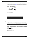
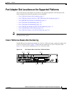
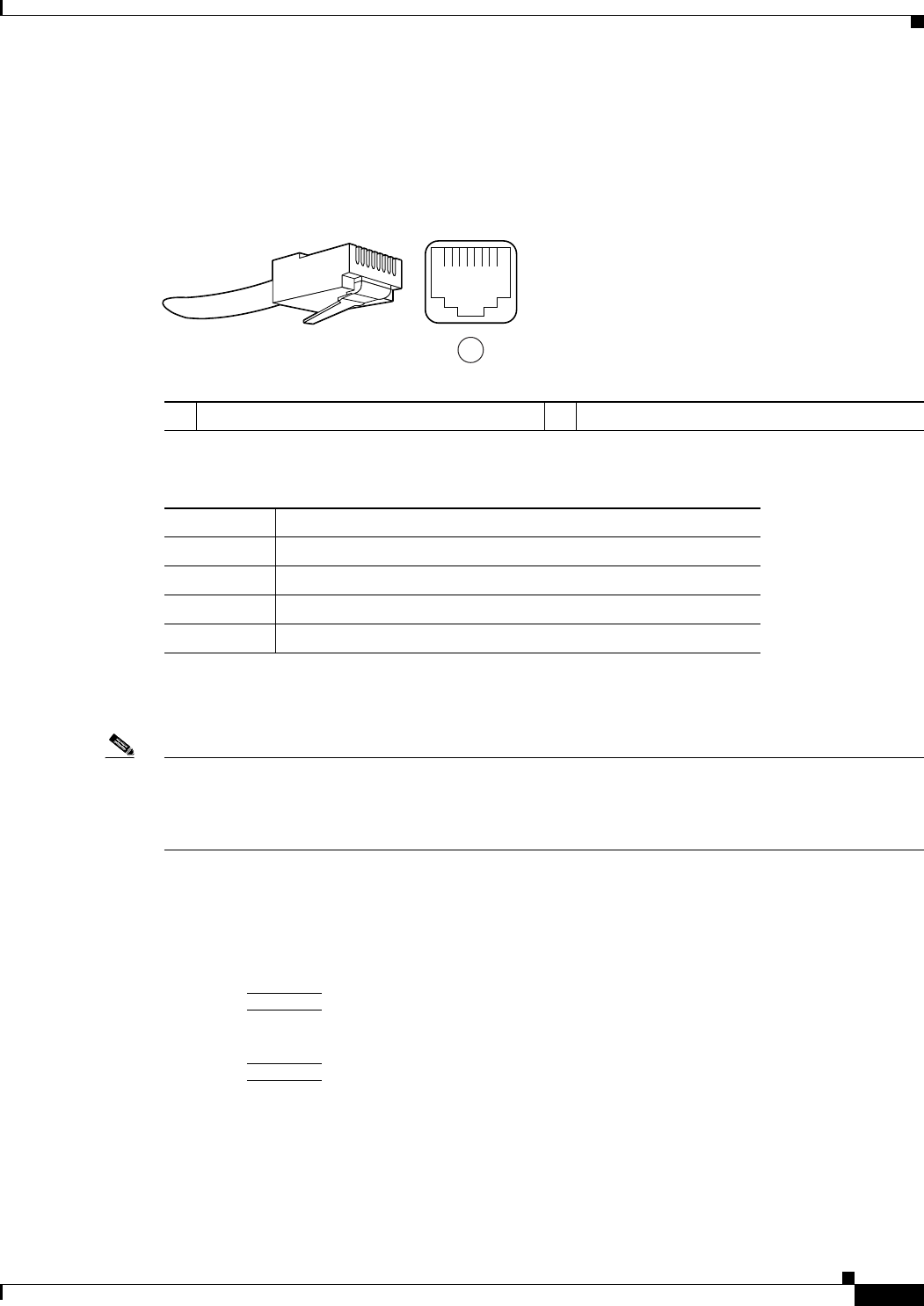
Figure 1-5 shows the RJ-45 cable connectors. Cisco does not supply Category 5 UTP RJ-45 cables; they
are available from a commercial supplier. Table 1-3 lists the pinouts and signals for the PA-2FE-TX
RJ-45 connectors.
Figure 1-5 RJ-45 Port and Connector
Note Referring to the RJ-45 pinout in Table 1-3, proper common-mode line terminations should be used for
the unused Category 5, UTP cable pairs 4/5 and 7/8. Common-mode line termination reduces the
contributions to electromagnetic interference (EMI) and susceptibility to common-mode sources. Wire
pairs 4/5 and 7/8 are passively terminated in the RJ-45 100BASE-TX port circuitry in the PA-2FE-TX.
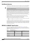
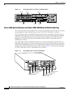
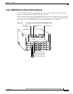
Depending on your RJ-45 interface cabling requirements, use the pinouts in Figure 1-6 and Figure 1-7.
Figure 1-6 Straight-Through Cable Pinout—PA-2FE-TX RJ-45 Connection to a Hub or Repeater
1 RJ-45 connector and port
Table 1-3 IRJ-45 Port Pinout Information
Pin Description
1TxD+
1
1. TxD = Transmit data
2TxD–
3RxD+
2
2. RxD = Receive data
6RxD–
84529
12345678
1
Ethernet port Hub
1 TxD+
2 TxD–
3 RxD+
6 RxD–
1 RxD+
2 RxD–
3 TxD+
6 TxD–
38582