


3-14
PA-2FE-TX and PA-2FE-FX Two-Port Fast Ethernet Port Adapter Installation and Configuration
OL-3474-07
Chapter 3 Removing and Installing Port Adapters
Port Adapter Removal and Installation
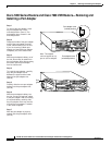
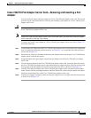
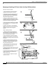
Removing and Installing a VIP Carrier Card in the Cisco 7500 Series Router
39395
E
JE
C
T
S
LO
T 0
S
LO
T
1
N
O
R
M
A
L
C
P
U
H
A
LT
R
E
S
E
T
A
U
X
.
C
O
N
S
O
L
E
ROUTE SWITCH PROCESSOR
C
L
A
S
S
1
L
A
S
E
R
P
R
O
D
U
C
T
L
A
S
E
R
P
R
O
D
U
K
T
D
E
R
K
L
A
S
S
E
1
P
R
O
D
U
IT
L
A
S
E
R
D
E
C
L
A
S
S
E
1
P
R
O
D
U
C
T
O
L
A
S
E
R
D
E
C
L
A
S
S
E
1
ENHANCED GIGABIT ETHERNET
L
I
N
K
E
N
A
B
L
E
D
T
X
R
X
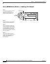
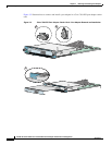
Captive
installation
screw
A
B
C
D
Card carrier guide
Captive
installation
screw
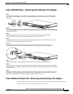
Remove a module as follows:
1. Use a screwdriver to loosen the captive
installation screws (shown in A and D).
2. Simultaneously pull the ejector levers out
to release the module from the backplane
connector (shown in B). The levers should
snap into their spring retainers.
3. Grasp the module handle with one hand
and place your other hand under the carrier
to support and guide the module as you pull it
out of the slot. Avoid touching the card.
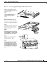
4. Place the removed module on an antistatic
mat or antistatic foam, or immediately install
it in another slot.
5. Install a new module or a filler (MAS7K-
BLANK) to keep dust out of the chassis and
to maintain proper airflow through the
chassis.
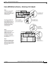
Install a module as follows:
1. Choose a slot for the new module and
ensure that there is enough clearance to
accommodate any interface equipment that
you will connect directly to its ports.
2. Use a screwdriver to loosen the captive
installation screws (shown in A) and remove
the filler (or the existing module) from the slot
to be filled.
3. Hold the module handle with one hand,
and place your other hand under the carrier
to support the module and guide it into the
slot. Avoid touching the card.
4. Place the back of the module in the slot
and align the guide on the carrier with the
groove in the slot (shown in A).
5. Carefully slide the module into the slot until
the faceplate makes contact with the ejector
levers (shown in C).
6. Use the thumb and forefinger of each hand
to push the ejector lever flat against the
module (shown in B).
7. Use a screwdriver to tighten the captive
installation screws.