


7-16
Software Configuration Guide—Release 12.2(25)SG
OL-7659-03
Chapter 7 Environmental Monitoring and Power Management
Power Management
Power Management for the Catalyst 4006 Switch
The power management feature for the Catalyst 4006 switch is designed to support an optimized
Catalyst 4006 chassis with a limited module configuration on a reduced number of power supplies.
The Catalyst 4006 chassis supports only the 400 W AC, 400 W DC, and 650 W DC power supplies and
allows you to mix AC-input and DC-input power supplies in the same chassis. In systems with redundant
power supplies, both power supplies should be of the same wattage. If you mix a 400 W power supply
and a 650 W power supply, the switch performs as if there were two 400 W power supplies. For detailed
information on supported power supply configurations for each chassis, refer to the Catalyst 4000 Series
Installation Guide.
Each Catalyst 4500 series module has different power requirements; thus, some switch configurations
require more power than 1+1 redundancy mode (a single power supply) can provide. In those
configurations, redundancy requires three power supplies. Redundant and nonredundant power
configurations are discussed in later sections of this chapter.
The Catalyst 4006 switch contains holding bays for up to three power supplies. You need two primary
power supplies to operate a fully loaded Catalyst 4006 chassis. You can set the power redundancy to two
primary plus one redundant power supply (2+1 redundancy mode) or to one primary plus one redundant
power supply (1+1 redundancy mode). The 1+1 redundancy mode might not support a fully loaded
chassis.
If your switch has only two power supplies and is in 2+1 redundancy mode (the default mode), there is
no redundancy. You can create redundancy with only two power supplies by setting the power
redundancy to operate in 1+1 redundancy mode (one primary plus one redundant power supply).
However, 1+1 redundancy will not support all configurations.
The 1+1 redundancy mode is designed and optimized for the following hardware configurations:
• One Catalyst 4006 chassis with a WS-X4014 supervisor engine with two 400 W power supplies (in
1+1 redundancy mode) and four WS-X4148-RJ or WS-X4148-RJ21 modules
• One Catalyst 4006 chassis with a WS-X4014 supervisor engine with two 650 W power supplies (in
1+1 redundancy mode) and five WS-X4148-RJ or WS-X4148-RJ21 modules
Although other configurations are possible, we do not recommend that you use them without careful
consideration of the power usage in the system. For example, other similar and possible configurations
may consist of four modules that consume less power, and the total module power usage does not exceed
the absolute maximum power usage for the system.
The supervisor engine uses 110 W, the fan box uses 25 W, and the backplane does not consume any
power. The system total load for the modules + supervisor + fan cannot total more than the power
supplied by the power supply. The 1+1 redundancy mode might not support a fully loaded chassis and,
therefore, one slot of the chassis might be empty. An attempt to use five modules risks an
oversubscription of available power.
If you opt to use the 1+1 redundancy mode, the type and number of modules supported are limited by
the power available from a single power supply. To determine the power consumption for each module
in your chassis, see the “Powering Down a Module” section on page 7-19.
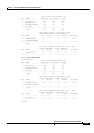
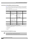
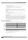
One-side 220 V+220 V,
other side 220 V
1360 40 4700 5493
Both sides at 220 V+220 V 1360 40 6800 7600
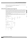
Table 7-5 Power Output in Combined Mode (continued)
Power Supply 12 V 3.3 V -50 V Total