


8-6
Software Configuration Guide—Release 12.2(25)SG
OL-7659-02
Chapter8 Configuring Power over Ethernet
When you use PoE modules with type 1/2 shielded twisted pair (STP) cable configurations (90 and 125
meters), the modules perform the same as with Category 5 cable for the IEEE 802.3af standard at 10 and
100 Mbps.
The following adapters have been tested and are the only ones supported by Cisco:
• LanTel Silver Bullet (SB-LN/VIP-DATA adapter)
• BIP-1236/S (BATM)
• RIT P/N 13712017
• RIT balun with integrated unshielded twisted pair (UTP) cable, 6 and 24 foot lengths
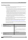
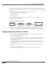
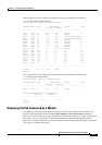
The following topology is supported:
Figure 8-1 Supported Adapter Topology
In Figure 8-1, a Catalyst 4500 series switch is connected to a balun through a short length of Category
5 UTP cable. Type 1 or Type 2 STP cable connects this balun to a second balun. A short length of
Category 5 UTP cable connects the second balun to another Powered Device (such as a Cisco IP phone).
Displaying the Operational Status for an Interface
Each interface has an operational status which reflects the PoE status for an interface. The operational
status for an interface is defined as one of the following:
• on—Power is supplied by the port.
• off—Power is not supplied by the port. If a powered device is connected to an interface with external
power, the switch does not recognize the powered device. The “Device” column in the show power
inline command displays as n/a.
• Power-deny—The supervisor engine does not have enough power to allocate to the port, or the
power that is configured for the port is less than the power required by the port; power is not being
supplied by the port.
• err-disable—The port is unable to provide power to the connected device that is configured in static
mode.
• faulty—The port failed diagnostics tests.
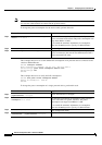
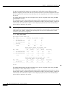
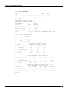
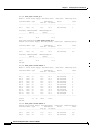
You can use the show power inline command to view the operational status for an interface.
UTP Cable
Balun
Type 1/2
STP Cable
UTP Cable
Catalyst 4500
series switch
Balun
Powered
Device
(Cisco IP Phone)
120556