


CHAPTER
11-1
Software Configuration Guide—Release 12.2(25)SG
OL-7659-03
11
Configuring Layer 2 Ethernet Interfaces
This chapter describes how to use the command-line interface (CLI) to configure Fast Ethernet and
Gigabit Ethernet interfaces for Layer 2 switching on Catalyst 4500 series switches. It also provides
guidelines, procedures, and configuration examples. The configuration tasks in this chapter apply to Fast
Ethernet and Gigabit Ethernet interfaces on any module, including the uplink ports on the supervisor
engine.
This chapter includes the following major sections:
• Overview of Layer 2 Ethernet Switching, page 11-1
• Default Layer 2 Ethernet Interface Configuration, page 11-4
• Layer 2 Interface Configuration Guidelines and Restrictions, page 11-5
• Configuring Ethernet Interfaces for Layer 2 Switching, page 11-5
Note To configure Layer 3 interfaces, see Chapter 22, “Configuring Layer 3 Interfaces.”
Note For complete syntax and usage information for the switch commands used in this chapter, refer to the
Catalyst 4500 Series Switch Cisco IOS Command Reference and related publications at
http://www.cisco.com/univercd/cc/td/doc/product/software/ios122/122cgcr/index.htm.
Overview of Layer 2 Ethernet Switching
The following sections describe how Layer 2 Ethernet switching works on Catalyst 4500 series switches:
• Understanding Layer 2 Ethernet Switching, page 11-1
• Understanding VLAN Trunks, page 11-3
• Layer 2 Interface Modes, page 11-4
Understanding Layer 2 Ethernet Switching
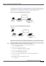
Catalyst 4500 series switches support simultaneous, parallel connections between Layer 2 Ethernet
segments. Switched connections between Ethernet segments last only for the duration of the packet. New
connections can be made between different segments for successive packets.