


15-5
Software Configuration Guide—Release 12.2(25)SG
OL-7659-03
Chapter 15 Understanding and Configuring Multiple Spanning Trees
Overview of MST
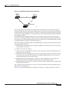
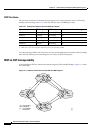
To STP running in the SST region, an MST region appears as a single SST or pseudobridge, which
operates as follows:
• Although the values for root identifiers and root path costs match for all BPDUs in all
pseudobridges, a pseudobridge differs from a single SST bridge as follows:
–
The pseudobridge BPDUs have different bridge identifiers. This difference does not affect STP
operation in the neighboring SST regions because the root identifier and root cost are the same.
–
BPDUs sent from the pseudobridge ports may have significantly different message ages.
Because the message age increases by one second for each hop, the difference in the message
age is measured in seconds.
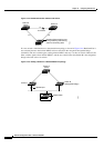
• Data traffic from one port of a pseudobridge (a port at the edge of a region) to another port follows
a path entirely contained within the pseudobridge or MST region. Data traffic belonging to different
VLANs might follow different paths within the MST regions established by MST.
• The system prevents looping by doing either of the following:
–
Blocking the appropriate pseudobridge ports by allowing one forwarding port on the boundary
and blocking all other ports.
–
Setting the CST partitions to block the ports of the SST regions.
Common Spanning Tree
CST (802.1Q) is a single spanning tree for all the VLANs. In a Catalyst 4000 family switch running
PVST+, the VLAN 1 spanning tree corresponds to CST. In a Catalyst 4000 family switch running MST,
IST (instance 0) corresponds to CST.
MST Instances
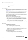
This release supports up to 16 instances; each spanning tree instance is identified by an instance ID that
ranges from 0 to 15. Instance 0 is mandatory and is always present. Instances 1 through 15 are optional.
MST Configuration Parameters
MST configuration has three parts, as follows:
• Name—A 32-character string (null padded) that identifies the MST region.
• Revision number—An unsigned 16-bit number that identifies the revision of the current MST
configuration.
Note You must set the revision number when required as part of the MST configuration. The
revision number is not incremented automatically each time you commit the MST
configuration.
• MST configuration table—An array of 4096 bytes. Each byte, interpreted as an unsigned integer,
corresponds to a VLAN. The value is the instance number to which the VLAN is mapped. The first
byte that corresponds to VLAN 0 and the 4096th byte that corresponds to VLAN 4095 are unused
and always set to zero.
You must configure each byte manually. You can use SNMP or the CLI to perform the configuration.