


10-11
Software Configuration Guide—Release 12.2(25)SG
OL-7659-03
Chapter 10 Understanding and Configuring VLANs, VTP, and VMPS
VLAN Trunking Protocol
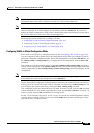
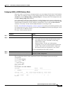
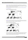
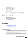
Figure 10-2 shows a switched network without VTP pruning enabled. Interface 1 on Switch 1 and
Interface 2 on Switch 4 are assigned to the Red VLAN. A broadcast is sent from the host connected to
Switch 1. Switch 1 floods the broadcast and every network device in the network receives it, even though
Switches 3, 5, and 6 have no interfaces in the Red VLAN.
You can enable pruning globally on the Catalyst 4500 series switch (see the “Enabling VTP Pruning”
section on page 10-13).
Figure 10-2 Flooding Traffic without VTP Pruning
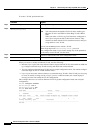
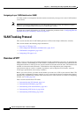
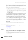
Figure 10-3 shows the same switched network with VTP pruning enabled. The broadcast traffic from
Switch 1 is not forwarded to Switches 3, 5, and 6 because traffic for the Red VLAN has been pruned on
the links indicated (Interface 5 on Switch 2 and Interface 4 on Switch 4).
Figure 10-3 Flooding Traffic with VTP Pruning
Enabling VTP pruning on a VTP server enables pruning for the entire management domain. VTP pruning
takes effect several seconds after you enable it. By default, VLANs 2 through 1000 are eligible for
pruning. VTP pruning does not prune traffic from pruning-ineligible VLANs. VLAN 1 is always
ineligible for pruning; traffic from VLAN 1 cannot be pruned.
Catalyst series
switch 4
Catalyst series
switch 5
Catalyst series
switch 3
Catalyst series
switch 6
Catalyst series
switch 1
Catalyst series
switch 2
Interface 1
Interface 2
Red
VLAN
94151
Switch 4
Switch 5
Switch 3Switch 6 Switch 1
Switch 2
Interface 1
Interface 2
Red
VLAN
31075
Interface 4
Interface 5
Flooded traffic
is pruned.