86 Chapter 5
Planning for Installation and Operation
5.3 Electrical Specifications and Requirements for Single-Phase Subsystems
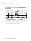
5.3.1 Internal Cable Diagram
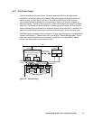
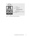
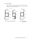
Figure 5.4 and Figure 5.5 illustrate the internal cable layout of single-phase 9960 and 9910
subsystems, respectively.
PS
PC
PS
PC
PS
PC
PS
PC
PS
PC
PS
PC
PC
PS PS
9960 Controller
:PCI Cable
:Internal PCI Cable
PC: Power Control
To CPU
Max.8
PS
PC
PS
PC
PCI I/F
Con.
PC
••••
DKC Panel
PS
PC
PS
PC
PS
PC
PS
PC
Disk Array
Unit
PS: AC Box (DKU-F405I-1PS, DKC-F410I-1PS)
Disk Array
Unit
Disk Array
Unit
Disk Array
Unit
Disk Array
Unit
Disk Array
Unit
↓
: AC Cable Kit consists of the following:
- USA use DKU-F405I-1UC and DKC-F410I-1UC.
- Europe use DKU-F405I-1EC and DKC-F410I-1EC.
Figure 5.4 Internal Cable Diagram of a Single-Phase 9960 Subsystem


