


96 Chapter 5
Planning for Installation and Operation
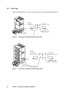
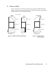
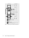
5.5 Floor Loading and Cable Routing Requirements
5.5.1 Service Clearance Requirements
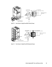
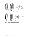
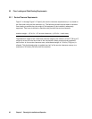
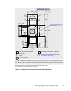
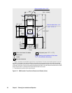
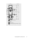
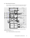
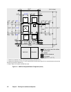
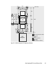
Figure 5.14 through Figure 5.17 specify the service clearance requirements (a + b) based on
the floor load rating and the clearance (c). The following formula can be used to calculate
floor loading to ensure that the weight of all equipment to be installed is adequately
supported. Total area is defined as machine area plus half the service clearance.
machine weight + (15 lb/ft
2
× 0.5 service clearance) + (10 lb/ft
2
× total area)
total area
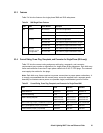
The additional weight of the raised floor and the weight of the cables is 10 lb/ft
2
(50 kg/m
2
)
uniformly across the total area used in the calculations. When personnel and equipment
traffic occur in the service clearance area, a distributed weight of 15 lb/ft
2
(75 kg/m
2
) is
allowed. This distributed weight is applied over half of the service clearance area up to a
maximum of 30 inches (760 mm) from the machine.