


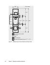


104 Chapter 5
Planning for Installation and Operation
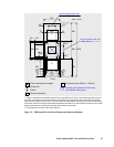
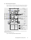
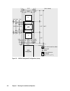
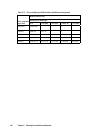
(Unit: inches)
31.5”
94.5”
Front
3.5”
3.5”
20.5”
2.6”2.6”
22.3”
.6”
.6” 26.3
3.9”
3.9”
19.7”
27.6”
31.5”
31.5”
G
Floor cutout area for cables
Caster
Screw jack
Service clearance
G
Grid panel
(over 17.7” x 17.7”)
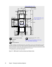
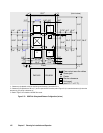
26.9”
2.3”
2.3”
5.8”
5.8”
19.9”
15.8
7.9”
7.9”
11” d
C *1
*1
a
b
*1
G
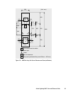
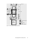
9910
Subsystem
*2
Figure 5.21 9910 Disk Subsystem All Configurations (inches)