


Hitachi Lightning 9900™ User and Reference Guide 101
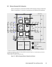
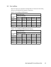
5.5.2 Minimum Subsystem Disk Configuration
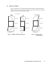
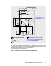
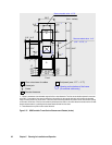
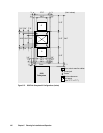
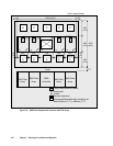
Figure 5.18 and Figure 5.19 illustrate the 9960 and 9910 subsystem minimum configuration.
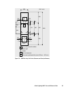
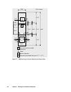
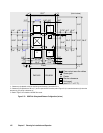
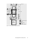
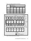
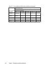
Figure 5.20 and Figure 5.21 illustrate all configurations of the 9960 and 9910 subsystems.
c *1
250
*3
*2
118
118
60
225
b *1a *1
G
Caster
Screw jack
680
60
60
115
115
570
(Unit: mm)
800
200
530
2400
Floor cutout area for cables
Service clearance
70
300
250
*3
680
60
564
400
*3
90
460 8657886
300
166
418166
1350
600718
16
16
Front
150
241
800
800
DKC410I DKU405I
G
G
Grid panel
(over 450mm x 450mm)
d
G
G
*1: Clearance (a+b) depends on the floor load rating and clearance c (see section 5.5.3).
*2: Clearance (d) is required over 0.28 m so as to open the DKC front door (refer to Figure 5.14). In case that clearance (d) is less than
clearance (a), give priority to clearance (a).
*3: Refer to Figure 5.14 for details on the DKC floor cutout.
Figure 5.18 9960 Disk Subsystem Minimum Configuration (millimeters)