


DS8100A
2
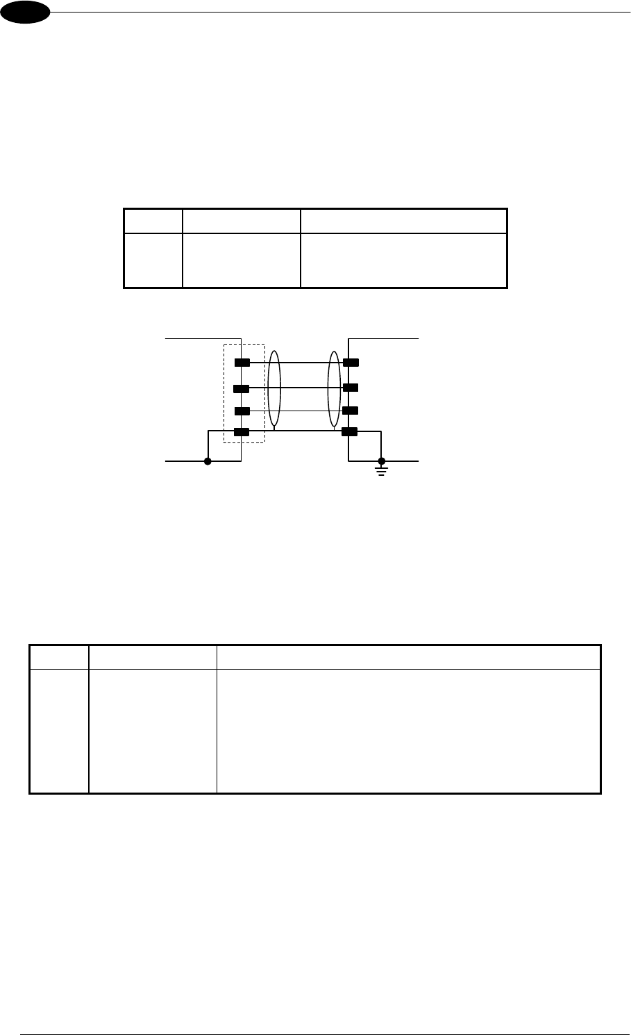
Auxiliary Interface
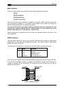
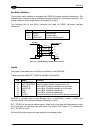
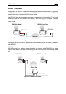
The auxiliary serial interface is equipped with RS232 full-duplex interface connections. The
interface type is exclusive and is selectable through the Genius™ configuration program. The
overall maximum cable length should not exceed 15 m (50 ft).
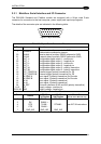
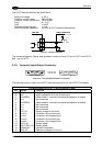
The following pins of the 26-pin connector are used for RS232 full-duplex interface
connection:
Pin Name Function
20 RXAUX Receive data
21 TXAUX Transmit data
23 SGND AUX Auxiliary signal ground
DS8100A
USER INTERFACE
23
GNDAU
X
GND
TXD
RXAUX
20
RXD
TXAU
X
21
1
Earth
Ground
CHASSIS
Figure 13 - RS232 Auxiliary Interface Connections
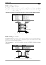
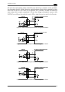
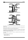
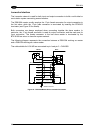
Inputs
The inputs of the reader are on the 26-pin connector of the DS8100A.
These inputs are called EXT_TRIG/PS, IN2/ENC, IN3 and IN4.
Pin Name Function
18 EXT_TRIG/PS A External trigger (polarity insensitive) for PS
19 EXT_TRIG/PS B External trigger (polarity insensitive) for PS
6 IN2/ENC A Input signal 2 (polarity insensitive) for Encoder
10 IN2/ENC B Input signal 2 (polarity insensitive) for Encoder
14 IN3A Input signal 3 (polarity insensitive)
15 IN4A Input signal 4 (polarity insensitive)
24 IN_REF Common reference of IN3 and IN4 (polarity insensitive)
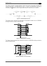
IN2/ENC is normally used for the Encoder input. In PackTrack™ mode, it detects the
conveyor speed. The maximum Encoder frequency is 2 KHz.
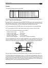
EXT_TRIG/PS is the main presence sensor. When active, this input tells the scanner to scan
for a code and that decoding can take place. The yellow LED (Figure C, 3) indicates the
EXT_TRIG/PS is active.
IN3 and IN4 can be used as the stop signal for the reading phase.
14