


INSTALLATION
2
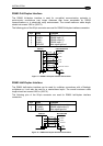
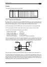
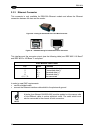
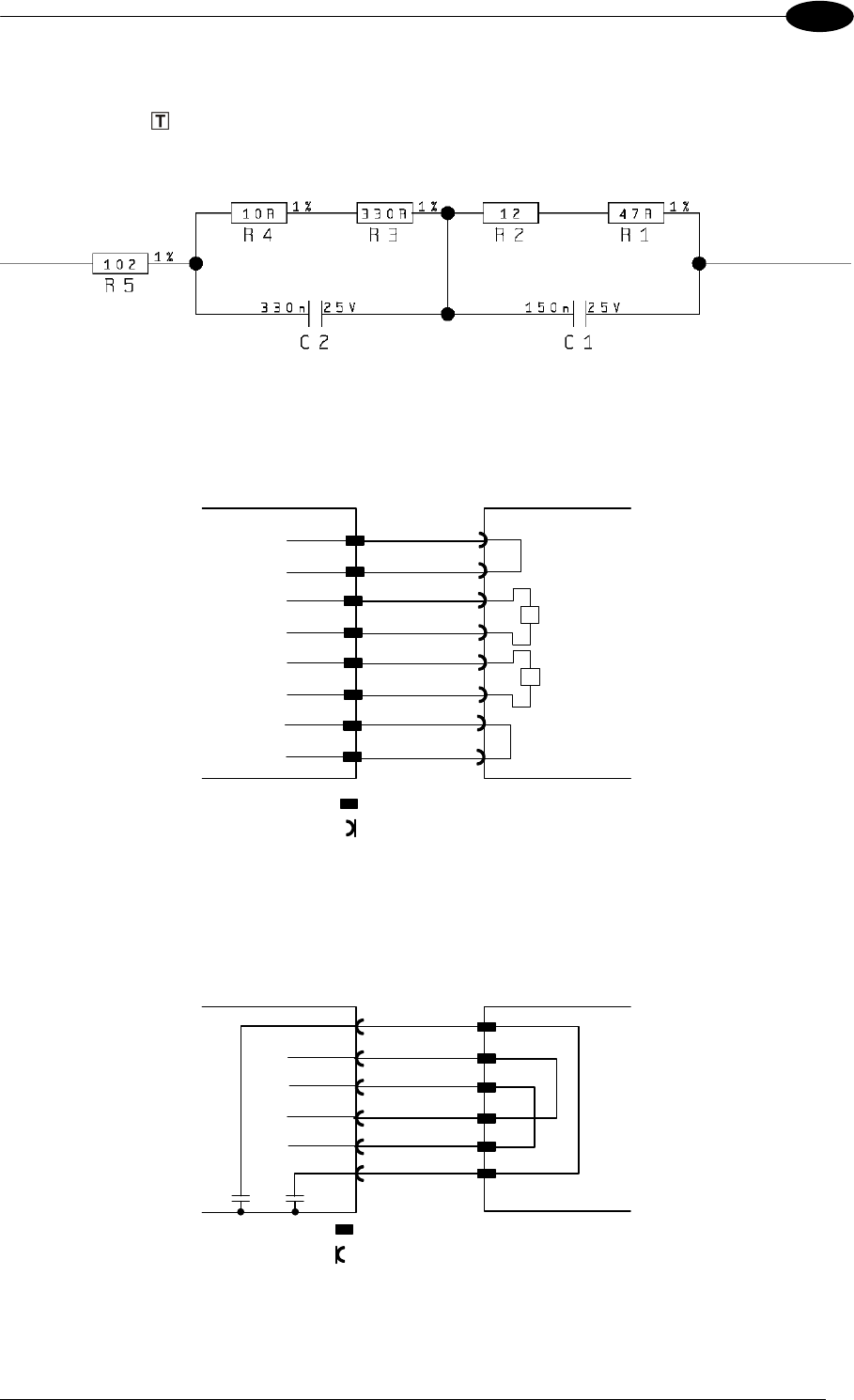
The following diagrams represent different network terminations using either the BTK-8102
Lonworks terminator or the BTK-8100 bus return. In Figure 27 the BTK-8102 terminator is
indicated by the
element, while the figure below shows its electrical circuit in details:
Figure 26 – BTK-8102 Electrical Circuit
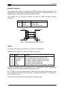
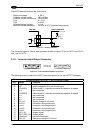
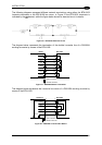
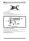
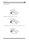
The diagram below represents the termination of the double Lonworks line of a DS8100A
working as master by means of the BTK-8102.
Master
BTK-8102
= male connector
= female connector
9
7
8
A2
7
A2
A1
9
8
A1
LON A+
LON A-
VS
VS_I/O
GND
T
REF_I/O
11
10
11
10
LON B+
LON B-
T
15
15
Figure 27 – DS8100A Master Termination
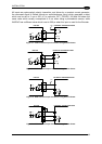
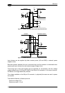
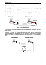
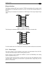
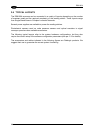
The diagram below represents the Lonworks bus return of a DS8100A working as slave by
means of the BTK-8100.
Last Slave BTK-8100
= male connecto
r
= female connecto
r
9
8
1
LON A+
LON A-
9
8
11
10
LON B+
LON B-
11
10
1
3
3
Shields
Figure 28 – DS8100A Lonworks Bus Return
21