


DS8100A
2
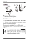
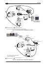
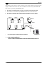
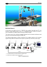
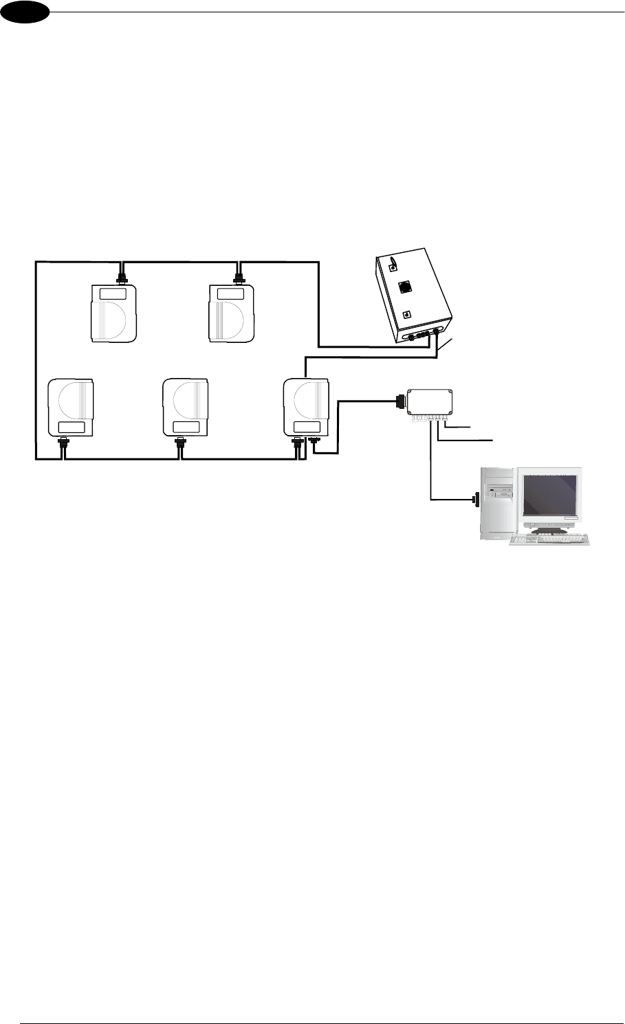
The following image shows a system consisting of five readers where the external signals
(trigger, encoder, serial to host, etc.) are connected to the master through the C-BOX 100.
The system is powered by the PWR-240 where:
• the master is connected through CAB-860X, which also provides bus termination
• the last slave is connected through CAB-830X, which also provides bus return.
• the master and all slaves are connected together through the CAB-810X cables
CAB810X CAB830X
CAB810X
PWR-240
Slave 4
Slave 3
CAB860X
Slave 2
Slave 1
C-BOX 100**
CAB601X
Maste
r
P.S.*
Encoder***
Local Host
CAB810X
CAB810X
* P.S. (Presence Sensor) connected to External Trigger/PS input.
** C-BOX 100 modified to accept scanner power.
*** Encoder connected to IN2/ENC input.
Figure 45 – Small Synchronized Network with more than 2 Readers and Single Power Unit
34