


DS8100A
2
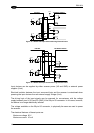
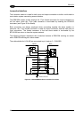
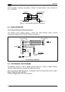
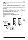
Note that GND is internally connected to chassis. The cable shield is also connected to
pin 1 - CHASSIS.
DS8100A
USER INTERFACE
23/25
GND
V- (Ground)
V+ (20 – 30 Vdc)
VS
9/13
CHASSIS
1
Earth Ground
Chassis
Figure 33 – Power Supply Using the 26-pin Connector
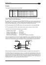
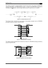
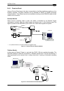
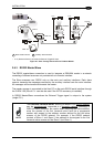
2.4 USER INTERFACE
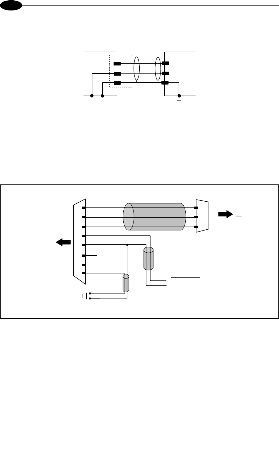
How To Build A Simple Interface Test Cable:
The following wiring diagram shows a simple test cable including power, external
(push-button) trigger and PC RS232 COM port connections.
26-pin D-sub female
23
20
GND
RXAUX
TXAUX
21
DS8100A
25
13
GND
VS
9-pin D-sub female
GND
TX
RX
PC
2
3
5
18
9
EXT TRIG A
VS
Power Supply
VS (20 – 30 VDC)
Power GND
Trigger
EXT TRIG B
19
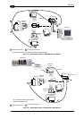
Test Cable for DS8100A
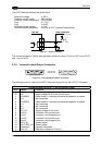
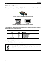
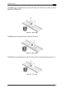
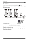
2.5 POSITIONING THE SCANNER
The DS8100A scanner is able to decode barcode labels at a variety of angles, however
significant angular distortion may degrade reading performance.
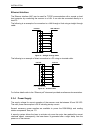
When mounting the DS8100A take into consideration these three ideal label position angles:
Pitch 0°, Skew 0° to 45° and Tilt 0°.
Follow the suggestions for the best orientation:
24