


NOTE: If you have unlatched the cable management arm, relatch it. For information about the
cable management arm, see the system’s rack documentation.
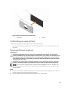
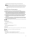
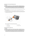
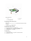
4. Connect the safety ground wire.
5. Install the DC power connector in the power supply unit.
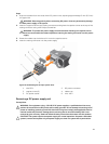
CAUTION: When connecting the power wires, ensure that you secure the wires with the strap
to the power supply handle.
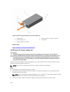
6. Connect the wires to a DC power source.
NOTE: When installing, hot-swapping, or hot-adding a new power supply, wait for 15 seconds
for the system to recognize the power supply and determine its status. The power-supply
status indicator turns green to signify that the power supply is functioning properly.
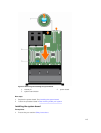
System board
Removing the system board
Prerequisites
CAUTION: Many repairs may only be done by a certified service technician. You should only
perform troubleshooting and simple repairs as authorized in your product documentation, or as
directed by the online or telephone service and support team. Damage due to servicing that is
not authorized by Dell is not covered by your warranty. Read and follow the safety instructions
that came with the product.
CAUTION: If you are using the Trusted Platform Module (TPM) with an encryption key, you may
be prompted to create a recovery key during program or System Setup. Be sure to create and
safely store this recovery key. If you replace this system board, you must supply the recovery key
when you restart your system or program before you can access the encrypted data on your hard
drives.
CAUTION: Do not attempt to remove the TPM plug-in module from the motherboard. Once the
TPM plug-in module is installed, it is cryptographically bound to that specific motherboard. Any
attempt to remove an installed TPM plug-in module breaks the cryptographic binding, and it
cannot be re-installed or installed on another motherboard.
1. Ensure that you read the Safety instructions.
2. Follow the procedure listed in Before working inside your system.
3. Remove the following:
a. cooling shroud
b. cooling fan assembly
c. power supply unit(s)
d. all expansion card risers
e. integrated storage controller card
f. internal dual SD module
g. internal USB key (if installed)
h. PCIe card holder
i. cable retention bracket
j. heat sink(s)/heat sink blank(s)
k. processors(s)/processor blank(s)
113