


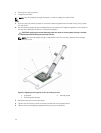
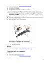
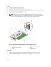
3. Remove the cooling shroud.
4. Remove the expansion card riser 1.
5. Keep the Phillips #2 screwdriver ready.
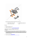
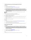
Steps
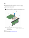
1. Align the end of the integrated storage controller card with the controller card connector on the
system board.
2. Lower the connector side of the integrated storage controller card into the integrated storage
controller card connector on the system board.
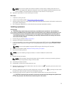
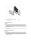
Ensure that the tabs on the system board align with the screw holes on the integrated storage
controller card.
3. Align the screws on the integrated storage controller card cable with the screw holes on the
connector.
4. Tighten the screws to secure the integrated storage controller card cable with the integrated storage
controller card connector on the system board.
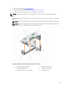
Next steps
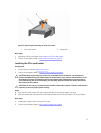
1. Replace the expansion card riser 1.
2. Replace the cooling shroud.
3. Follow the procedure listed in After working inside your system.
Expansion cards and expansion card risers
NOTE: A missing or an unsupported expansion card riser logs a System Event Log (SEL). It does not
prevent your system from powering on. A no BIOS POST message or F1/F2 pause is displayed.
Expansion card installation guidelines
Depending on your system configuration, the following PCI Express (PCIe) generation 3 expansion cards
are supported:
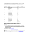
Table 4. Supported expansion cards
Riser PCIe slot Processor
connection
Height Length Link
width
Slot width
1 1 Processor 2 Low Profile Half Length x8 x16
1 2 Processor 2 Low Profile Half Length x8 x16
1 3 Processor 2 Low Profile Half Length x8 x16
2 4 Processor 2 Full Height Full Length x16 x16
2 5 Processor 1 Full Height Full Length x8 x16
3 (default) 6 Processor 1 Full Height Full Length x8 x16
3 (alternate) 6 Processor 1 Full Height Full Length x16 x16
3 (default) 7 Processor 1 Full Height Full Length x8 x16
NOTE: To use PCIe slots 1 through 4 on the riser, both the processors must be installed.
NOTE: The expansion card slots are not hot-swappable.
82