


1-8 User’s Guide
Disadvantage:
• Must ensure that the failover cluster nodes have ample resources available to
handle the additional workload.
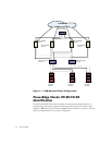
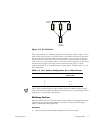
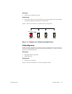
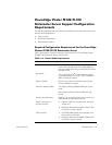
Figure 1-3 shows an example of multiway failover configuration.
Figure 1-3. Example of a 4-Node Multiway Failover
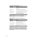
Table 1-4 provides an example of a multiway failover configuration for the cluster
shown in Figure 1-3. For each cluster resource group, the failover order in the
Preferred Owners list outlines the order that you want that resource group to failover.
In this example, node 1 owns cluster resource groups A, B, and C. If node 1 fails, the
cluster resource groups A, B, and C will failover to cluster nodes 2, 4, and 3, respec-
tively. The cluster resource groups on cluster nodes 2, 3, and 4 need to be configured
similarly.
NOTE: When implementing this type of failover solution, failback should be config-
ured to avoid performance degradation.
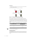
Cascading Failover
With Cascading failover, all running applications migrate from the failed node to the
next preassigned cluster node. If you do not make a failover selection, cascading
failover will be the default failover type. This type of failover provides the following
features:
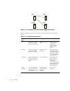
Table 1-4. Example of a 4-Node Multiway Failover Configuration
Cluster Resource Group Failover Order in the
Preferred Owners List
A 1, 2, 3, 4
B 1, 4, 2, 3
C 1, 3, 4, 2
cluster
node 1
cluster
node 2
cluster node 3 cluster node 4
Application A
Application B
Application C