support.dell.com SAN Components 10-7
Connecting a PowerVault 130T DLT Library and
PowerVault 35F Fibre Channel Bridge to a Cluster-
Attached PowerVault SAN
You can add tape backup devices to your PowerVault SAN to provide additional backup
to your cluster. To implement this configuration, use the PowerVault 35F Fibre Chan-
nel SCSI bridge to support the PowerVault 130T DLT library on PowerEdge Cluster
FE100 Datacenter Server configurations.
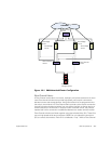
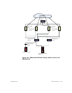
Figure 10-2 shows a supported PowerEdge Cluster FE100/FL100 Datacenter configu-
ration using redundant Fibre Channel switches, Fibre Channel bridge, and PowerVault
130T DLT library. In this configuration, each of the cluster nodes is attached to the
backup device and the backup local disk resources, as well as to the owned cluster
disk resources. Using this configuration provides you the ability to add more servers
and storage systems in the future, if needed.
NOTES: See the storage and tape backup documentation for more information on
configuring these components.
Contact the tape backup software vendor for more information on using your software
in a cluster configuration.
The PowerVault 35F Fibre Channel SCSI bridge, the PowerVault 130T DLT library, and
their cables are made through a single switch fabric and do not comprise a redundant
configuration. Therefore, tape backups may be incomplete if one of these compo-
nents fails.
Configuring Hard-Disk Drive Letters Using Multiple
Shared Storage Units
Before installing the Cluster Service, ensure that both nodes have the same view of
the shared storage. Because each node has access to hard-disks that are in a com-
mon storage array, each node must be assigned identical hard-disk drive letters.
To ensure that the hard-disk drive letter assignments for the cluster nodes, perform
the following procedures:
1. Ensure that your cables are connected properly.
The Windows 2000 Disk Management utility displays all of the accessible disks
attached to the first QLogic HBA, followed by those that are accessible from the
second QLogic HBA.
On the first HBA, the attached disks will be displayed numerically, starting with
the lowest port number.
2. Ensure that the first QLogic HBA detected by each cluster node is connected to
the switch attached to PowerVault storage processor A.
3. Ensure that the second QLogic HBA detected by each cluster node is connected
to the switch attached to the PowerVault storage processor B.


