


Removing and Replacing Parts 4-1
Chapter 4
Removin
g
and Replacin
g
Parts
T
his chapter provides procedures for removing and replacing components,
assemblies, and subassemblies.
Unless otherwise noted, each of the procedures in this chapter assumes the
following:
•
The computer and any attached peripherals are turned off and the peripher-
als are disconnected from the computer’s I/O panel.
•
A part can be replaced or installed by performing the removal procedure in
reverse order.
When performing the procedures in this chapter that require the display assem-
bly to be open, use a book or something similar to support the display assembly.
The angle of the display assembly with respect to the base assembly should not
exceed 180 degrees for a 12.1-inch LCD and 170 degrees for a 13.3-inch LCD.
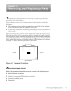
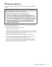
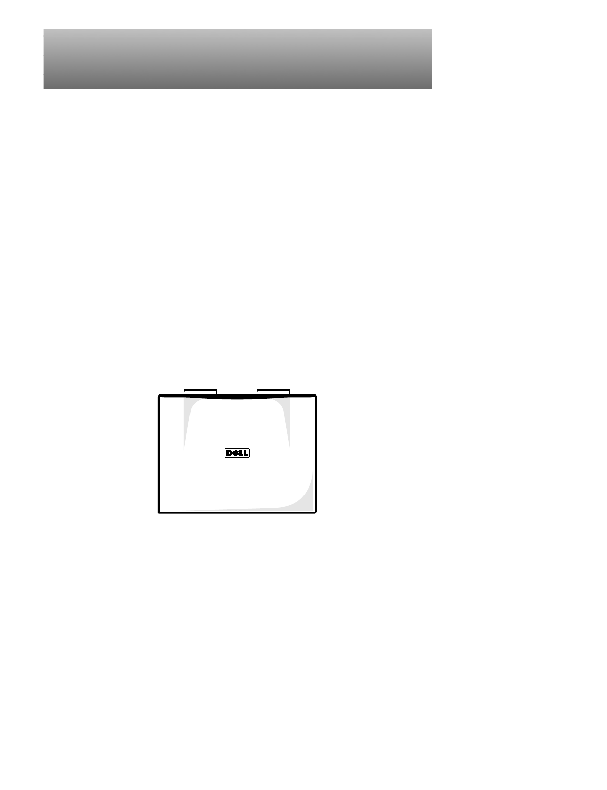
Also, assume that locations or directions relative to the computer are as shown
in Figure 4-1 unless otherwise specified in a procedure.
Figure 4-1. Computer Orientation
R
ecommended Tools
Most of the procedures require the use of one or more of the following tools:
•
Small flat-blade screwdriver
•
Number 1 magnetized Phillips-head screwdriver
•
Antistatic grounding strap
•
Dental pick
right side left side
back of computer
front of computer