


Removing and Replacing Parts 4-37
L
CD Assembly
The LCD assembly consists of the display assembly and its related components.
This section describes how to remove either the 12.1-inch or 13.3-inch LCD
assembly. Later sections in this chapter provide removal and replacement proce-
dures for the components of the LCD assembly.
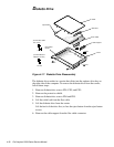
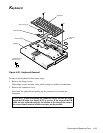
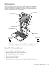
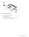
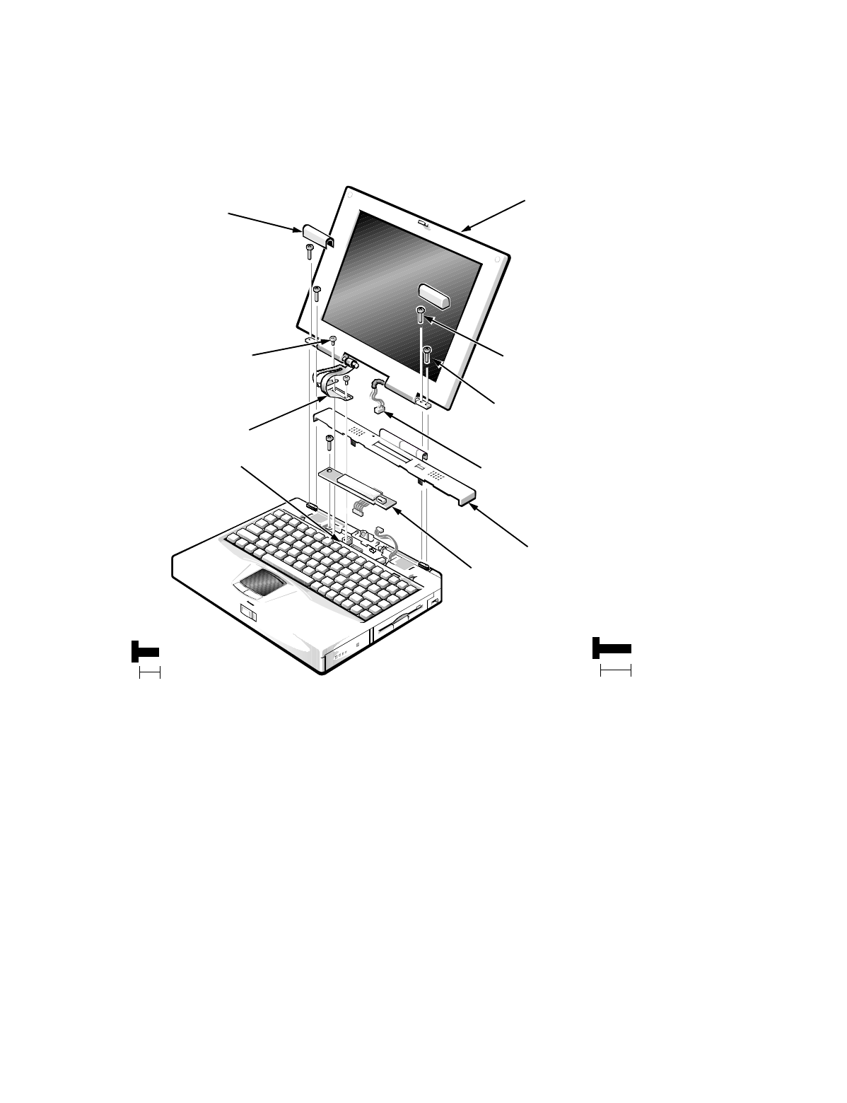
Figure 4-23. LCD Assembly Removal
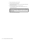
To remove the LCD assembly, follow these steps:
1. Remove the hinge covers and the connector cover.
See “Keyboard” found earlier in this chapter.
2. Remove the status display panel.
3. Disconnect the inverter cable.
The inverter cable is a cable harness on the right side of the LCD assembly.
LCD assembly
hinge covers (2)
H1
H2
H3
H4
connector cover
(screws H1–H4
are 8 mm)
inverter cable
LCD flex cable
G1
G2
(screws G1 and
G2 are 5 mm)
NOTE: This is a figure of a 12.1-inch LCD assembly. The 13.3-inch LCD
assembly has an LCD wiring harness instead of an LCD flex cable.
connectors JP8 or JP1
status display panel
8 mm
5 mm