


68 Installing System Components
Installing an Optical or Tape Drive
CAUTION: Only trained service technicians are authorized to remove the system cover and access any of the
components inside the system. Before performing any procedure, see your Product Information Guide for
complete information about safety precautions, working inside the computer and protecting against electrostatic
discharge.
1
Unpack the drive and prepare the drive for installation.
For instructions, see the documentation that accompanied the drive.
If you are installing a SCSI tape drive
, you must have a SCSI
controller card installed (see "Installing
an Expansion Card
" on page 70
) and configure the tape drive according to the documentation that
came with the tape drive, based on the following guidelines:
a
Each device attached to a SCSI host adapter must have a unique SCSI ID number. (Narrow SCSI
devices use IDs 0 to 7; wide SCSI devices use IDs from 0 to 15.) Set the drive’s SCSI ID to avoid
conflicts with other devices on the SCSI bus. For the default SCSI ID setting, see the
documentation provided with the drive.
NOTE: There is no requirement that SCSI ID numbers be assigned sequentially or that devices be attached to
the cable in order by ID number.
b
SCSI logic requires that the two devices at opposite ends of a SCSI chain be terminated and that
all devices in between be unterminated. Therefore, you enable the tape drive’s termination if it is
the last device in a chain of devices (or sole device) connected to the SCSI controller.
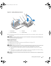
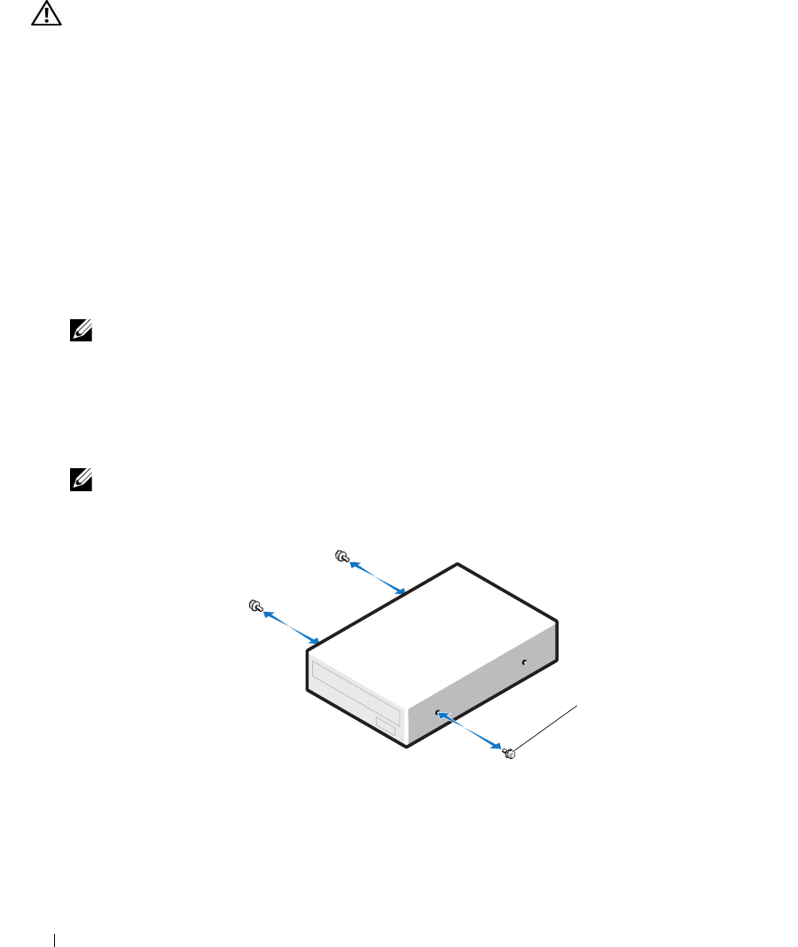
2
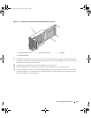
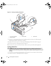
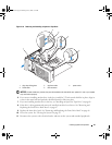
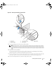
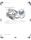
Attach the three shoulder screws to the drive. See Figure 3-19.
NOTE: Spare shoulder screws are attached to the inside of the front drive bezel insert.
Figure 3-19. Installing Optical or Tape Drive Shoulder Screws
3
Turn off the system, including any attached peripherals, and disconnect the system from the electrical
outlet.
1 screws (3)
1
book.book Page 68 Monday, June 5, 2006 1:51 PM