


92 Installing System Components
6
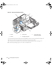
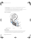
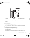
Disconnect the following cables from the system board. See Figure 6-2.
• Two power-supply cables from the POWER1 and POWER2 connectors
• If applicable, diskette data cable from the DSKT connector
• I/O panel cable from the FRONT PANEL connector
• 5.25-inch device data cable from the IDE connector
• Memory cooling fan cable from the FAN_MEM connector
• If applicable, data cable(s) from the SATA connector(s)
7
Remove all expansion cards and any attached cables. See "Removing an Expansion Card" on page 72.
8
Remove all memory modules. See "Removing Memory Modules" on page 79.
NOTE: Record the memory-module socket locations to ensure proper reinstallation of the memory modules.
CAUTION: The processor and heat sink can become extremely hot. Allow sufficient time for the processor and
heat sink to cool before handling.
NOTICE: To prevent damaging the processor, do not pry the heat sink off of the processor.
9
Remove the processors. See "Removing the Processor" on page 73.
10
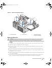
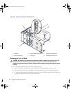
Using a #2 Phillips screwdriver, remove the nine system board mounting screws that secure the system
board to the chassis. See Figure 3-31.
NOTE: To remove all of the screws, you need a Phillips screwdriver with a blade at least 6 inches long.
book.book Page 92 Monday, June 5, 2006 1:51 PM