


Installing System Components 91
d
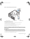
Place the I/O panel board on the mounting bracket, routing the thermal diode cable under the
board, and slide the board to the side to engage the hooks in the mounting bracket slots.
e
Reinstall the screw connecting the I/O panel board to the mounting bracket.
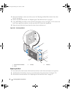
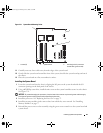
2
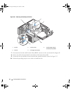
Fit the I/O panel bracket assembly into the holding tab on the front of the chassis. See Figure 3-30.
3
Secure the I/O panel bracket assembly by installing the I/O panel assembly mounting screw.
4
Connect the cables the new I/O panel that you removed in step 5 of "Removing the Front I/O Panel"
on page 89.
5
Reinstall the front bezel. See "Replacing the Bezel" on page 88.
6 Rotate the hard-drive carrier back into the system. See
"Rotating the Hard-Drive Carrier Into the
System" on page 46
.
7
Close the system. See "Closing the System" on page 43.
8
Reconnect the system to the electrical outlet, and turn on the system.
Thermal Diode Cable (Service Only Parts Procedure)
To replace a faulty thermal diode cable, follow the steps in "Removing the Front I/O Panel" on page 89 to
remove the front I/O panel and remove the old thermal diode cable. Then, install the new cable and
reinstall the front I/O panel as described in "Replacing the Front I/O Panel" on page 90.
System Board (Service Only Parts Procedure)
CAUTION: Only trained service technicians are authorized to remove the system cover and access any of the
components inside the system. Before performing any procedure, see your Product Information Guide for
complete information about safety precautions, working inside the computer and protecting against electrostatic
discharge.
CAUTION: The heat sink can get hot during operation. To avoid burns, ensure that the system has sufficient time
to cool before removing the system board.
Removing the System Board
1
Turn off the system and attached peripherals, and disconnect the system from the electrical outlet.
2
Remove the system cover. See "Opening the System" on page 43.
3
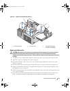
Rotate the hard-drive carrier out of the system. See "Rotating the Hard-Drive Carrier Out of the
System" on page 44.
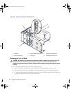
4
Remove the processor access door assembly:
a
Remove the green screw that attaches the processor access door assembly to the system board and
to the system chassis.
b
Lift to remove the processor access door assembly from the system.
5
Remove the card and front fans. See "Replacing the Card and Front Fans" on page 83.
book.book Page 91 Monday, June 5, 2006 1:51 PM