


58 Installing System Components
3
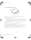
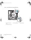
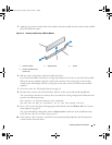
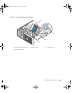
To open the card retention door, press the two release tabs inward. See Figure 3-13.
4
If you are installing a new card, remove the filler bracket.
NOTE: Keep this bracket in case you need to remove the expansion card. Filler brackets must be installed
over empty expansion-card slots to maintain FCC certification of the system. The brackets also keep dust and
dirt out of the system and aid in proper cooling and airflow inside the system.
5
Prepare the card for installation.
See the documentation that came with the card for information on configuring the card, making
internal connections, or otherwise customizing it for your system.
NOTE: Some NICs automatically start the system when they are connected to a network.
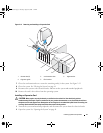
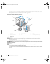
6
Insert the card into the expansion card connector on the system board (SLOT1, SLOT2, SLOT3,
SLOT4, or SLOT5) and press down firmly. Ensure that the card is fully seated in the slot and all cards
and filler brackets are flush with the alignment bar.
See Figure 6-2 for the location of the five
expansion card connectors.
7
Close the card retention door to secure the card(s) in the system.
NOTICE: Do not route card cables over or behind the cards. Cables routed over the cards can prevent the system
cover from closing properly or cause damage to the equipment.
8
Connect any cables that should be attached to the card.
See the documentation for the card for information about the card’s cable connections.
9
Close the system. See "Closing the System" on page 41.
10
Reconnect the system to the electrical outlet, and turn on the system and attached peripherals.
11
Install any device drivers required for the card as described in the documentation for the card.
SAS Controller Expansion Card
Read the installation instructions in the documentation for your SAS controller card. Install the card in
expansion card connector SLOT2 (see "Installing an Expansion Card" on page 57), and connect the
hard-drive activity indicator cable from the card to the AUX_LED connector on the system board (see
Figure 6-2 for the connector location). See "Hard Drives" on page 51 for information about connecting
hard drives.
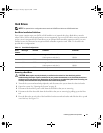
Memory
The four memory module connectors on the system board can accommodate from 512 MB to 4 GB of
533-MHz and 667-MHz unbuffered ECC DDR II single or dual-rank memory modules. See Figure 6-2
for the location of the four memory module connectors.
NOTE: As shown in Figure 6-2, memory slots are not in numeric order on the system board. When installing
memory, take care to install it in the proper slots according to the configuration guidelines in Table 3-2. Installing
memory in the wrong slots will significantly reduce system performance.
book.book Page 58 Tuesday, August 25, 2009 1:14 PM