


Installing System Components 77
• SATA hard-drive data cable(s) from the SATA connector(s)
• Intrusion switch cable from the INTRUDER connector
4
Remove all expansion cards and any attached cables. See "Removing an Expansion Card" on page 56.
5
Remove all memory modules. See "Memory" on page 58.
NOTE: Record the memory-module socket locations to ensure proper reinstallation of the memory modules.
CAUTION: The processor and heat sink can become extremely hot. Allow sufficient time for the processor and
heat sink to cool before handling.
NOTICE: To prevent damaging the processor, do not pry the heat sink off of the processor.
6
Remove the processor. See "Removing the Processor" on page 62.
7
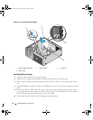
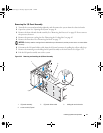
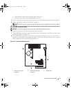
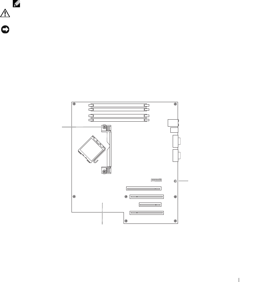
Using a #2 Phillips screwdriver, remove the eight system board mounting screws that secure the system
board to the chassis. See Figure 3-23.
8
Using a #2 Phillips screwdriver, remove the two processor heat sink pivot mount screws and remove
the pivot mount from the system board. See Figure 3-23. The heat sink pivot mount screws are green
and are longer than the system board mounting screws.
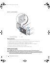
Figure 3-23. System Board Mounting Points
1 heat sink pivot mount
screws (2)
2 system board mounting
screws (8)
3 system board
1
2
3
book.book Page 77 Tuesday, August 25, 2009 1:14 PM