


Transferring Calls Using Release Link Trunk Transfer
November 2009 204
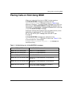
For more information on L4L3mENABLE_PROTOCOL and
L3L4mALERTING, please refer to Volume 5, Bfv API Reference
Manual. For more information on the
Brooktrout Configuration Tool,
refer to the chapter on using the configuration tool in the installation
and configuration guide that came with your software.
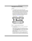
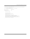
Call Control Sequence Diagrams
The charts below describe call transfer n using BSMI, both with the
RLT functionality of the DMS-250, and the traditional method (for
purposes of comparison).
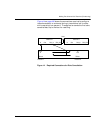
In both calls, the board receives an incoming call and determines
that the call needs to be rerouted to an alternate destination. In the
non-RLT call transfer configuration, the application initiates an
outbound call to the reroute destination and uses the TSI matrix to
pass incoming data from the call originator to the reroute
destination.
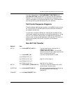
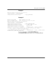
Non-RLT Call Transfer
Network Host
SETUP ===> L3L4mSETUP_IND (B1) The host receives the incoming call on
B-channel #1. From the
IISDN_CALLED_PARTY info, the host
determines that this call needs to be rerouted
to an alternate branch office.
===> L3L4mSET_TSI
src=IISDNtsiLINE_A+1
dst=IISDNtsiLINE_A+2
src=IISDNtsiLINE_A+2
dst=IISDNtsiLINE_A+1
The host cross-connects B1 and B2.
Map B1 to B2 on Span A.
Map B2 to B1 on Span A.
SETUP <=== L4L3mCALL_REQUEST (B2) The host initiates the outbound call on B2,
where the call transfer occurs.
ALERTING ===> L3L4mALERTING (B2) Call setup completes normally on B-channel
#2 with receipt of ALERTING and
CONNECT.
CONNECT
===> L3L4mCONNECT (B2)