


General Information
November 2009 275
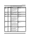
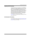
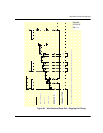
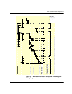
Timing Diagrams
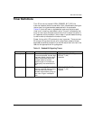
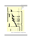
To aid in the development process, timing diagrams that illustrate
call setup and call teardown signaling in the various supported
protocols are provided in the sections that follow. The diagrams
consist of four parts:
IISDN SMI Messages: Indicates the Bfv API messages sent to
and received from the card during the call scenario.
IISDN Timers: The timers possibly in use during the call
scenario are listed, and active only during the periods on the
diagram where the graph blocks are shaded.
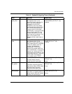
Receive and Transmit Signaling Bits: The thick black lines
represent the signaling bits used to represent the call states in
each protocol. Wink Start, Immediate Start/Fixed Pause and
Delay protocols use only one bit (A-bit) to carry information, so
only one line is shown for each direction. In these protocols, the
value of the A-bit is seen as the “hook switch state” (“on hook” is
low or zero, “off hook” is high or one). FXO/FXS Loop Start and
Ground Start protocols use 2 signaling bits, A and B, to carry
information, so two lines are shown for each direction. In these
protocols, the bit values represent current feed and ring signal
(FXO protocols), and hook state/ring current and ring ground
(FXS protocols).
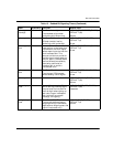
Arrows and Vertical Dashed Lines: The arrows and vertical
dashed lines indicate that there is a causal relationship between
an event that occurs to the start of other events. For instance,
the expiration of a timer can result in a change in the hook
switch state, or a change in hook switch state can result in the
start of a timer and issuance of an L3L4 message.
Note: The diagrams are designed to give the reader a general
understanding of the sequence of events for various robbed bit
protocols over time. The timers and spacing on the graphs are
not proportional to the actual events that occur.