


DSL-504 ADSL Router User’s Guide
50
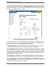
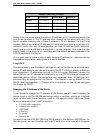
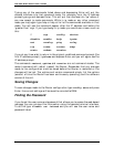
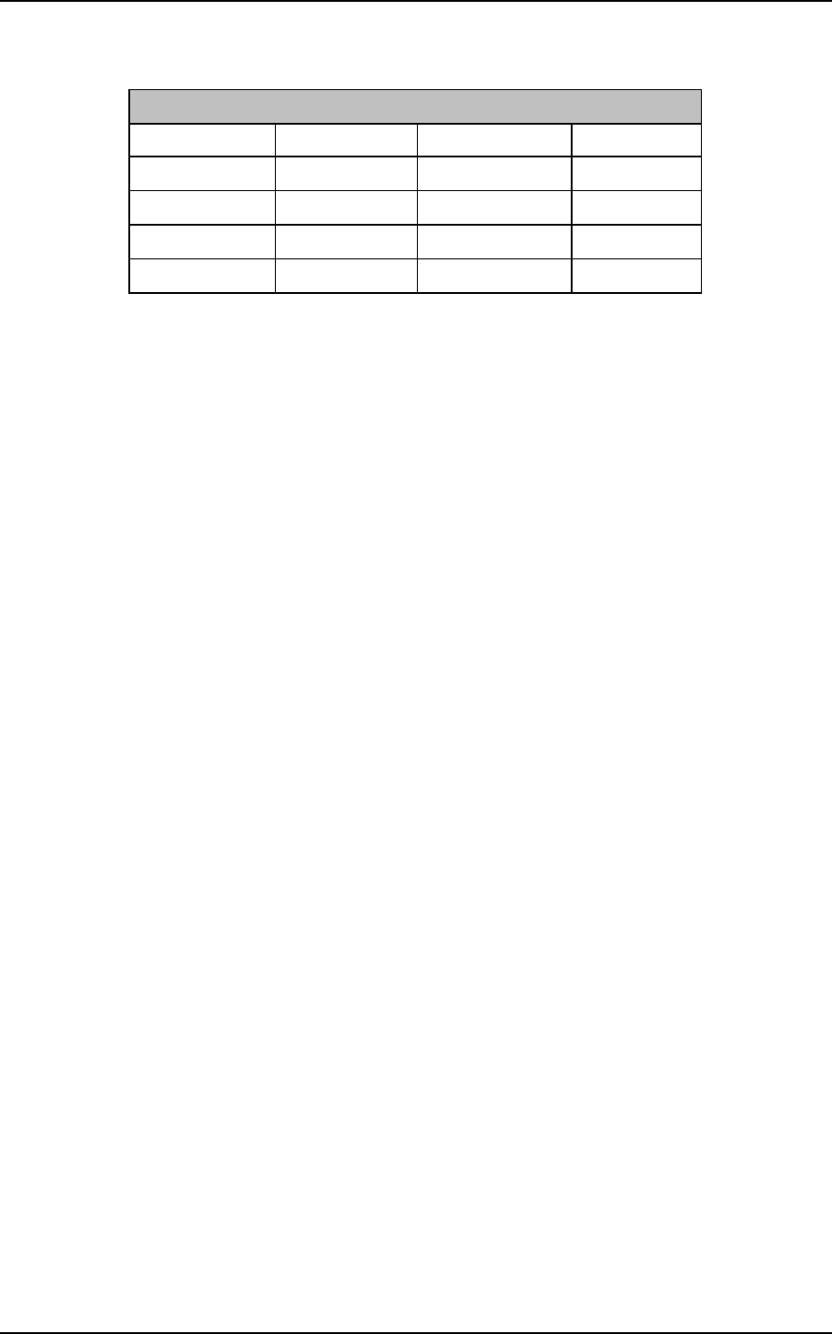
Default Addressing Example
Host
IP Address Subnet Mask Gateway IP
Router 192.168.0.1 255.255.255.0
Computer #1 192.168.0.2 255.255.255.0 192.168.0.1
Computer #2 192.168.0.3 255.255.255.0 192.168.0.1
Computer #3 192.168.0.4 255.255.255.0 192.168.0.1
Please note that when using the default IP address as in the above example, the
first three numbers in the IP address must always be the same with only the
fourth number changing (for a Class C network). This is because the first three
numbers define the network IP address (all machines must belong to the same IP
network), while the last number denotes the host IP address (each computer
must have a unique address to distinguish it on the network). Also note that the
subnet mask is the same for all machines and the default gateway address is the
LAN IP address of the Router.
It is a good idea to make a note of each device’s IP address for reference during
troubleshooting or when adding new stations or devices.
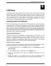
Using DHCP
The second way to use the default settings is to allow the Router to automatically
assign IP addresses to your computers using DHCP. To do this, simply make sure
your computers’ IP addresses are set to 0.0.0.0 (under Windows, choose the
option Obtain an IP address automatically in the TCP/IP network component
described above). When the computers are restarted, their IP settings will
automatically be assigned by the Router. The Router is set by default to use
DHCP. See the discussion in Chapter 5 for information on how to use configure
the Router for DHCP.
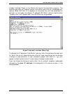
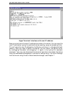
Changing the IP Address of the Router
If you choose to change the IP address of the Router you will need to access the
device directly via the RS-232 connection using a terminal emulation interface
(such as Microsoft HyperTerminal used in the sample screen captures). Your
terminal parameters will need to be set to:
• VT-100/ANSI compatible
• Terminal keys enabled
• 9,600 baud
• 8 data bits
• No parity
• One stop bit
Connect a standard RS-232 (DB-9 to DB-9) cable to the Router’s RS-232 port on
the rear panel, connect the other end to a PC with a terminal emulation program