


HARSFEN0602
9 Commutation
9.1 General
The harmonica drives fixed magnet motors.
The principle of all the fixed magnet motors is the same:
A winding creates a magnetic field. If the magnet is directed along the field lines of the
winding, the magnet is in its steady state, and the winding exerts no power on the magnet.
If the magnet is not along the winding field lines, the magnet will try to align with the field
lines.
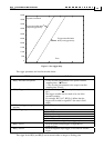
Mathematically,
)cos(IKT
e
θ⋅=
Angle between the magnet and the field of the winding
e
K
A parameter, proportional to the strength of the magnet
T Motor winding torque
I Motor current
If the magnet is allowed to move, it will rotate until aligned with the winding field, and
remain stationary there.
A motor is composed of a fixed magnet and several windings. The windings are arranged so
that each winding generates a field of different direction.
By powering the windings alternately, the direction of the windings field move, and so does
the direction to which the rotor is attracted.
The process of alternating the powered winding is called commutation.
Brush DC motors are equipped with a mechanical arrangement that select which winding to
power. In brushless motors, the windings to power are selected electronically.
The winding powering policy, or the commutation policy, has two major variants.
These variants are called Stepper and BLDC (Brushless DC).
The setting of the commutation parameters is normally done using the Composer
interface routine. If you want to tune commutation manually, read the CA[]
documentation in the Command Reference Manual thoroughly.
9.1.1 Brush DC motors
The Harmonica has three motor output connections. A DC motor has only two wires. In
order to drive a DC motor by the amplifier, connect the motor to the B and C motor phase
outputs, and leave the phase A connection open.
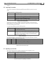
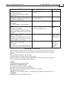
We next have to set the following parameters:
CA[28] Set to 1 for a DC motor
CA[18] Set encoder resolution just for reference. The value of CA[18] will not affect
anything in later activities
CA[16] Encoder direction: Set 0 or 1 so that the encoder will count forward in the desired
movement direction.
CA[25] Motor direction: Set 0 or 1 so that the motor will rotate to the desired direction for
positive torque commands.
The values of CA[16] and CA[25] MUST be correlated, otherwise the feedback direction is
wrong - the encoder will count negative displacement for positive torques.
If the feedback direction is wrong, the motor will "run away" immediately upon attempting
speed or position control.
If you intend to use the Harmonica with DC motor, you may skip the rest of this
chapter.
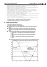
9.1.2 The Stepper Commutation Policy