


HARSFEN0602
WS[20] Stator field angle, in 1024 counts/rev units.
Stator field angle (deg) = WS[20]
(360/1024)
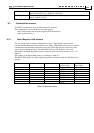
WS[21] Commutation counter. WS[21] counts the main high-resolution position
sensor, modulo CA[18].
9.3 Commutation sensors
For BLDC commutation, rotor position sensors are required.
The commutation sensors divide into two main groups.
- Direct field sensors that sense the magnetic field of the motor.
- Shaft position sensors.
9.3.1 Rotor Magnetic field sensors
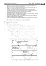
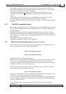
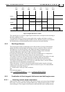
The first group consists mainly of digital Hall sensors. (Analog Hall sensors are less
common and the Harmonica doesn't know to use them). Digital Hall sensors may be used for
commutation with minimum calculation, since they reflect the direction of the rotor with
respect to the windings directly. The digital Hall sensors yield, however, only crude
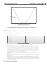
information. Standard digital Hall sensors divide the electrical period of motor to six – see
Figure 6.
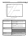
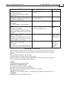
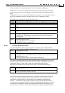
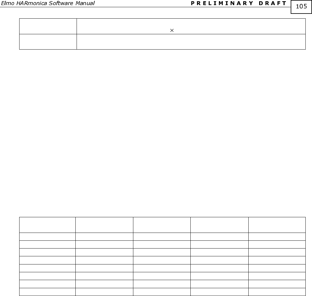
The reading of the digital Hall sensors is according to Table
9-1.
The BLDC field angle is the field angle that produces maximum torque for this Hall sensor
reading.
Hall A Hall B Hall C Electrical rotor
position (deg)
BLDC Field
angle (deg)
0 0 0 Illegal
1 0 0 330-30 90
1 1 0 30-90 150
0 1 0 90-150 210
0 1 1 150-210 270
0 0 1 210-270 330
1 0 1 270-330 30
1 1 1 Illegal
Table 9-1: Hall sensor values